Brick-1Channel-Relay
5V POWER CONTROL RELAY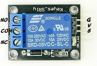

When we design projects using Arduino, we may need to control equipment with large current or high voltage requirements (such as electromagnetic valves) which cannot directly controlled by an Arduino digital output. A good solution is to use a relay.
This Electronic Brick includes a relay that can switch up to 10 Amps at 250 Volts AC. It mounts the relay on a small circuit board along with a driver transistor, LED, protective Diode, and pin connectors that match the 3-pin cables that come with the Electronic Brick Set.

To control the relay, you would plug a 3-pin cable on the relay pins (White to the left) with the other end to whatever output pin (2 to 13) you wish to use. Make sure the Arduino cable end plugs correctly: (white to top). The cables are color coded: BLACK is G (Ground), RED is V (Voltage) and WHITE is S (Signal).
A relay is really a SWITCH, but it is operated by a magnet inside, not by hand.
We have more information on using relays at these links.
- Arduino POWER
- (Scroll down on that page to: "How Relay Contacts Work:")
- More details about Relays
- A good Tutorial about Relays
- A few more practical considerations
How Relay Contacts Work:
Look at your relay. Notice the 3 screw-type terminals. They are labelled "NO", "COM", "NC". Those labels mean:
|
|
| RelayContacts1-450.jpg |

- NO: Normally Open
- COM: Common Connection
- NC: Normally Closed
Look at the diagram on the right. This shows the switch that is inside the relay. This switch is "thrown" by the electromagnet inside. The diagram shows that COM is connected to the Normally Closed contact. That's the case when the relay is off. When the relay is turned on the electromagnet flips the switch up and COM is then connected to Normally Open. So, if we want a lamp to be on when the relay is on, we connect our circuit from COM to NO.