Brick-Pushbuttons&OtherSwitches
ELECTRONIC BRICKS THAT ARE ON-OFF "SWITCHES"

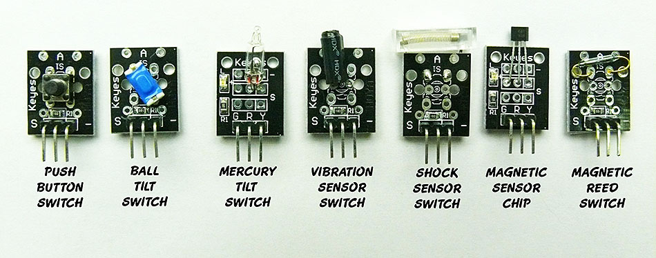
There are many different Input Devices that are really switches.. but many of them look different and have different ways they are operated. The "Electronic Bricks" shown above are part of the YourDuino Electronic Brick Set.
EXAMPLES (Left to Right above):
- The PUSHBUTTON Switch (operated by you!)
- The BALL TILT SWITCH (Has a small loose metal ball inside)
- The MERCURY TILT SWITCH (Has a small ball of mercury inside a glass tube)
- The VIBRATION SENSOR SWITCH (Has a tiny wire with an attached weight, and contacts)
- The SHOCK SENSOR SWITCH (Has a wire almost touching a spring)
- The MAGNETIC SENSOR CHIP (Has a 'Hall Effect' Integrated Circuit: switches when a magnet is near)
- The MAGNETIC REED SWITCH (A glass tube with two close-spaced contacts. A magnet makes them touch)
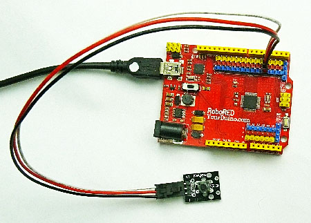
OK, how do we hook these up and make them work?? We use either the YourDuino RoboRED with 3-pin connectors built-in or a Sensor Shield plugged on top of a YourDuino328, YourDuino-UNO or other Arduino type board. Or a MEGA Sensor Shield plugged on top of a YourDuinoMEGA. Then we use Cables, like this:


The left photo shows the Push Button Switch brick plugged into the RoboRED with a 3-wire Cable. (See More About Cables HERE)
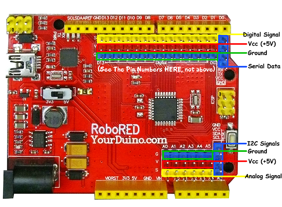
Details of the YourDuino RoboRED are above on the right. (More details HERE).
Hookup, and Software ...
OK, let's hook up a switch and try it out...
- Connect the "Push Button Switch" brick with a 3-wire cable to Digital I/O #3. Plug the "latched" end into the pushbutton brick and the flat end onto the RoboRED or Sensor Shield #3. (Make sure the White wire is connected to signal "S". NOTE The Red Arrow in the top photo). The labels "GVS" mean Ground(black), Voltage(red) and Signal(white).
- NOTE: The Pushbutton Switch Brick (and most others) connect the signal cable to Ground when the switch is pressed. See More About That Here!
- The RoboRED (and most Arduinos) have an onboard LED connected to Pin 13. We will use it.
- Start the Arduino IDE, and make sure you have the right Board and Serial Port selected by the "Tools" menu.
- Load and run the "Blink" program to make sure everything is set up correctly. The pin 13 LED on the board should blink on and off every second.
- Get a New blank IDE window (File > New) and copy and paste the following program (the part between the thin horizontal lines). Click "Verify" to make sure it's OK. Then click "Upload". You should see a message: "Done Uploading".
NOTE: Take your time and read the Software Sketches below slowly. There are some comments to tell you what the lines mean. And there will be a more detailed discussion of each Software Sketch.
(Continued after the program listing)
/* YourDuino Electronic Brick Test 1
 Simple Switch type INPUT DEVICES
 terry@yourduino.com */

/*-----( Declare Constants )-----*/
#define SWITCHPIN 3
#define LEDPIN    13

/*-----( Declare Variables )-----*/
int  switch_state;  /* Holds the last state of the switch */

void setup()   /*----( SETUP: RUNS ONCE )----*/
{
  pinMode(SWITCHPIN, INPUT);
  pinMode(LEDPIN, OUTPUT);

}/*--(end setup )---*/


void loop()   /*----( LOOP: RUNS CONSTANTLY )----*/
{

  switch_state = digitalRead(SWITCHPIN);
  if (switch_state == ! HIGH)
  {
    digitalWrite(LEDPIN, HIGH);
  }
  else
  {
    digitalWrite(LEDPIN, LOW);
  }
}/* --(end main loop )-- */

/* ( THE END ) */
Pushbutton Action:
The action you should see is simple: push the button and the LED will light.
We didn't need a computer to do that !
But what if you suddenly need the LED to be ON and when the pushbutton is pressed, turn OFF??
You can redesign that with one keystroke. Find the line:
if (switch_state == ! HIGH) and remove that "!" exclamation point before "HIGH", like this:
if (switch_state == HIGH)
Oh.. that "!" exclamation point character means NOT or invert in the code. Cool programmers read that character verbally as "BANG". And how do they say asterisk * ?? SPLAT of course :-)
This says "if switch_state == HIGH" so it changes the logic of your program. Try it out...
Upload that and test it.... OK? Now change it back, Upload and test..
Six Other Simple Switches:
Your Pushbutton should now again turn on the LED. Let's try some other simple switches:
Ball Tilt Switch:
Plug this Electronic Brick on the end of the cable that had the Pushbutton. Tilt the brick back and forth so that you can see the LED turn on and off and the ball inside rolls back and forth. This is another "Simple Switch".
Mercury Tilt Switch:
Plug this Electronic Brick on the end of the cable that had the Pushbutton. NOTE the connection is different, the white Signal wire goes to the right side. Tilt the brick back and forth so that you can see the small mercury drop move back and forth; you should also see the LED turn on and off. The brick also has a built-in LED. This is another "Simple Switch".
Vibration Sensor Switch:
Plug this Electronic Brick on the end of the cable that had the Pushbutton. Note the white wire goes to S (left). Tap the brick with your finger. Try different positions. You should see the LED blink on and off very rapidly. This is another "Simple Switch".
Shock Sensor Switch:
Plug this Electronic Brick on the end of the cable that had the Pushbutton. Note the white wire goes to S (left). This is a different type sensor. Hold the wire near the sensor and "flick" the sensor with you finger. It take a very sharp movement to fire it. You should see the LED blink on and off very briefly. This is another "Simple Switch".
Magnetic Sensor Chip: ("Hall Effect" : click here for the WikiPedia Explanation)
Plug this Electronic Brick on the end of the cable that had the Pushbutton.  Note the white wire goes to the right.
  Bring a magnet close to the small plastic "chip" at the end of the brick. Change the orientation of the magnet. You will probably see that the magnetic field direction has to be right to trigger the switch. You should see the LED turn on and off. This is another "Simple Switch".
Magnetic Reed Switch: (Click here for the Wikipedia Explanation)
Plug this Electronic Brick on the end of the cable that had the Pushbutton.  Note the white wire goes to the right.
  Bring a magnet close to the small glass 'reed switch' at the end of the brick. You should see the LED turn on and off. This is yet another "Simple Switch".
Simple Switch with Serial Monitor Output:
Here's the same software Sketch , but with 3 added lines to send the results to the "Serial Monitor" program. Save your current Sketch if you made changes you want to keep, get a new blank window and copy/paste this:
/* YourDuino Electronic Brick Test 2
 Simple Switch type INPUT DEVICES
 with Serial Monitor Output
 terry@yourduino.com */

/*-----( Declare Constants )-----*/
#define SWITCHPIN 3
#define LEDPIN    13

/*-----( Declare Variables )-----*/
int  switch_state;  /* Holds the last state of the switch */

void setup()   /*----( SETUP: RUNS ONCE )----*/
{
  pinMode(LEDPIN, OUTPUT);
  Serial.begin(9600);

}/*--(end setup )---*/


void loop()   /*----( LOOP: RUNS CONSTANTLY )----*/
{
  Serial.print("SWITCH IS - ");
  switch_state = digitalRead(SWITCHPIN);
  if (switch_state == LOW)
  {
    digitalWrite(LEDPIN, HIGH);
    Serial.println("LOW");
  }
  else
  {
    digitalWrite(LEDPIN, LOW);
    Serial.println("HIGH");
  }
  delay(250); /* Wait a bit to see display */
}/* --(end main loop )-- */

/* ( THE END ) */
Upload and run this version. Then click the "Serial Monitor" (rightmost button on IDE). Push the button or activate your switch. You should see the printed output scroll up the Serial Monitor screen, telling you if the switch is ON (LOW) or OFF (HIGH). You should be getting familiar with these "Digital Logic" Terms!
  To learn more about the Arduino "Serial Monitor" (click)..
Conclusion of this section:
We have used 7 different Digital Input Devices, and sent print to the Serial Monitor.

  You can use these basics to design and put together many different devices.