Brick-Resistors-LEDs
Jump to navigation
Jump to search
Determining LED Polarity:
Powering LEDs:
Arduino LED Circuits:
Brick-Resistors-LEDs


The different YourDuino.com sets and kits (See these) include many colored LEDs and resistors to use with them. We will show you how to connect and control LEDs, and how to know what resistors to use. Quick Answer: 220 ohms almost always works fine! Also the YourDuino Electronic Brick Set includes LEDs and Laser on small modules you can just plug in (right).
ABOUT LEDS:
A light-emitting diode (LED) is a semiconductor device that emits light when an electric current is passed through it. Light is produced when the internal particles that carry the current ( electrons and holes) recombine together within the semiconductor material. The LED itself is a tiny semiconductor die (chip) that is mounted inside plastic with metal leads coming out. (Photo upper right). The plastic is often the same color as the LED light, but blue and white LEDs have a clear plastic. How can you tell them apart?? Only by hooking them up :-)


 Different colors: Inside the semiconductor material of the LED, the electrons and holes are contained within energy bands. The separation of the bands (i.e. the bandgap) determines the energy of the photons (light particles) that are emitted by the LED. The photon energy determines the wavelength of the emitted light, and hence its color. Different semiconductor materials with different bandgaps produce different colors of light. The precise wavelength (color) can be tuned by altering the composition of the light-emitting, or active, region.

Determining LED Polarity: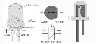

LEDs have a positive and negative terminal, defined as the anode(+) and cathode(-). The cathode should be connected towards the ground or negative side of the driving voltage source, and the anode toward the positive side. LEDs usually have their cathode marked in some manner. (See photo, right) On round LEDs the cathode is usually denoted with a flat indentation on it's side, and the anode lead is usually the longer lead.
Powering LEDs: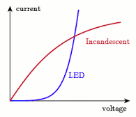

Most LEDs you will use are intended to be used with a DC current of about 20 Milliamperes (20 mA) flowing through them. This is 20/1000 of an ampere, 0.02 Amps. Also, Arduino should have it's output current limited to about 20 mA.
  You must control the current through the LED as too much current will damage it or the device it is connected to. LEDs have very different characteristics than the incandescent bulbs we used to use. (Graph at right). As the voltage goes up, the LED current suddenly goes up quickly. So it is difficult to operate LEDs with just voltage control and we need to control current instead. An Arduino digital output puts out almost 5 volts and if we connected it directly to an LED the current would be much too high. The easy way is to add a resistor (resistors, um, Resist current). We have found that a 220 ohm resistor works well for most small LEDs.

LED Voltage and Current VS Color:

BUT (That's a usual Electronics Engineer term ! ): Different color LEDs have somewhat different characteristics (graph at right). On the graph we see a Red LED has a voltage of about 2 volts at a current of 20 mA. BUT Green or Blue LEDs are at about 3.5 volts. Hmm.. As it turns out our usual 220 ohm resistor works OK for all of these. BUT you may want to actually calculate the right resistor value for your important application. There are several "LED calc" pages online; we like This One. And see This Great Tutorial by Wayne Storr.
 An Example: WhatIf you want to run a nice bright Green LED from an Arduino output and set the current at 20 mA? We need to know: "Applied Voltage" (about 4.8 volts actually coming from Arduino), "Diode Forward Voltage" (about 3.5 volts from the graph), and the "Forward Current" (We SAID 20 mA). CLICK for a solution: OK, nice, 68 ohms is the answer. You can change the values on that page as you need. See the diagram on the right to see how the Math works relative to the actual circuit. For this example: Rs = (Vs - Vf) / If The numbers: : 4.8-3.5 = 1.3 and 1.3 / .02 = 65 ohms. 68 is a standard resistor value. See? You can Do It Yourself (DIY).
Arduino LED Circuits: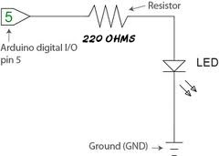

Oh.. how do we actually hook LEDs to Arduino?? You connect the Arduino I/O pin to the resistor and the LED to ground (figure on right). This is a "Series Circuit". The Resistor is used as a "current limiting resistor".

  We will link to other pages showing details of LEDs connected to Arduino. Soon...
MORE (About LEDs):
LEDs are comprised of compound semiconductor materials, which are made up of elements from group III and group V of the periodic table (these are known as III-V materials). Examples of III-V materials commonly used to make LEDs are gallium arsenide (GaAs) and gallium phosphide (GaP). Until the mid-90s LEDs had a limited range of colors, and in particular commercial blue and white LEDs did not exist. The development of LEDs based on the gallium nitride (GaN) material system completed the palette of colors and opened up many new applications, including white LEDs that use a blue LED with added phosphors.
  Want to see even more? WikiPedia(LED)
Dimming LEDS with PWM (Pulse Width Modulation): LINK
All About RGB LEDS (Click):
RGB Fade All Colors (Click):