DC-Motors-2
Jump to navigation
Jump to search
Introduction
(Written, Composed and Illustrated by Mike Cook) Thanks!
One of the great joys of computer programming is when something happens other than on the screen, and perhaps the best example of this is when that something is movement. Moving models of all kinds are not only exciting to control with your computer but also are very instructive in the techniques of control. There are many different types of motorised models that can be used. The Lego system of models allows perhaps the most flexible way of constructing moving models but there are others on the market. The one problem with commercial models is the computer interface. Where these are available they tend to be based on relays and are very expensive. On the Motors 1 page I looked at directly switching a motor with a transistor or a relay, Here I look at one of the many types of motor driver chips which offers great flexibility in driving not only motors but also other heavy loads.
The Basics
The output from Arduino pin can only supply in the order of about 40 mA. This is normally insufficient to drive any mechanical device so what we need to do is to boost this with a current amplifier. The LM18293 from National semiconductors consists of four such amplifiers capable of delivering 1 amp each, but the big advantage of these is that they have a push pull output. Note, a push pull output is not some strange creature dreamed up by Dr. Doolittle, it describes the way in which a circuit can switch.
Consider Figure I a. This switch can energise a load by connecting one end down to earth. When the switch is open then there is no connection at one end of the circuit we can say it pulls the current through the load. Figure 1 b is essentially the same only we can say the switch pushes current through the load. Now figure 1 c is a double pole switch, this can push or pull. In other words it can connect the load to either of the supply rails. Finally if you look at figure 1 d you will see the switch equivalent of one of the amplifiers in the LM18293. There is a push pull switch controlling the output as well as an enable switch allowing you to disconnect the load altogether. Of course in the LM18293 the switching is done by transistors but the effect is the same as a switch.
The Chip
The great advantage of a push pull output with enable is that it is so flexible, we can use it not only to turn a motor on and off but also to change its direction as well as to allow different types of motor breaking to be implemented.
Figure II shows the pin out of the LM18293.
Notice that there are in effect four identical buffers, each has an input and output. There are two enable lines so that each line controls two buffers. Also there are two positive supply connections, one for the switching signal and the other for the load. This is just what we need as often the motor's voltage is different from the 5 volts of the computer's logic. This supply voltage can range anywhere between 4.5 to 36 volts, and each output can switch up to 1 amp. The chip is constructed in a special way to help heat dissipation, four earth pins are connected together close to the centre of the carrier. These provide a good thermal contact into the heart of the chip. If you are using a printed circuit board you can make the heat sink part of the board as shown in the diagram. However if you are not doing this then you can always add a clip on heat sink.
Having said this, most applications will not need a heat sink at all. It will happily drive 1 watt in free air. As usual, the rule of thumb as to whether you need a heat sink or not is, can you keep your finger on it? If it is too hot for this, then you need a heat sink.
Driving a Motor
There are two basic ways in which you can power a motor in a single direction, you can have a common earth or a common supply. The only difference is whether a logic 1 turns the motor on or off. These two ways are shown in figure III.
Notice that across each motor there is a diode. This is because when you get the collapsing magnetic fields associated with motors there is a backwards voltage generated. This is called "the back EMF" (Electro Motive Force), the diode effectively shorts this out. I have shown the two different ways in figure III but you can use the same way on each buffer in your circuit. Now look at the table in figure III and you will see we have a number of different options. In the simplest system you can wire the enable input to 5 volts and simply control each motor from one of the digital output pins. You can even use one of the PWM pins on the Arduino to regulate the speed of the motor. This works by rapidly turning the motor on and of and the ratio of on time to off time determines the power you are feeding to the motor. This configuration will also give you flywheel breaking control of the motors.
Flywheel braking is the effect we get when we do not simply deprive a motor of power but short it out as well. If we simply remove the power then the kinetic energy in the rotor and shaft of the motor keep it going. What we have is, in effect, a generator. This produces a voltage in the same direction as that used to make the motor turn. However if we short circuit that voltage then the kinetic energy is quickly drained into the short circuit. Therefore when we do this the motor stops quickly.
If we do not want this effect of rapid motor stopping we can use the enable line to turn the motor off. However in that case you will have to turn both motors off at once.
In order to control the direction of a motor we need to be able to change the direction of current flow through it. To do this we need to use two buffers as shown in figure IV this is sometimes called a H-Bridge, you can see why from the way it is drawn.
Forgetting the enable for a moment we have two control inputs, if they are different the motor is on and if they are the same the motor is off. Here the diode arrangement is a little more complex as we can't swap the diode connections at the same time. Note that here, unlike the single direction case, the diodes that are forward biased are passing the full motor current. Therefore the diodes have to be able to pass as much current as the motor needs.
If we want to control the speed of this then the simplest arrangement is to apply the PWM signal to the enable line. However, you can PWM the signal line if you want but this is a little complex. Say, for example, you are PWMing pin 10 and using pin 15 as a direction control. When you are going clockwise (a zero on pin 15) then a logic one on the PWM signal will turn the motor on, therefor the numbers you send to the analogWrite() function should use to control the speed are normal, the bigger the number the faster it goes. Now when you are going clockwise you have the reverse situation; pin 15 has a logic one and a logic zero on the PWM signal (pin 10) will turn it on, therefore you need to use the inverse of the numbers you used in the other direction. That is easily generated, if the value of the number that sets the speed is in N then the inverse of the number will be:- 255 -N.
With four buffers in the LM18293 you can control four motors in a single direction or two motors bi-directionally. With PWM on the enable line you can control the speed of all the motors.
Isolation
Before we go, just a word about power supplies and motors. Generally motors can be electrically very noisy. This obviously depends on the type of motor but as a rule of thumb the less you paid for it the noisier it will be. If you power a motor from the computer's power supply, this noise can get back into the power lines and crash your computer. No permanent damage will occur but you will find it very frustrating if the computer crashes every time it turns on a motor. If this happens then the first thing to do is to power the motor from a separate power supply. Then if you still have trouble, you can try placing 0.1uF capacitors across the motor. In the unlikely event that you still get trouble you will need to isolate the power supply from the computer as, even though it is a separate one, it is still connected to the computer by the common zero volts or earth line. This can be done by using an opto-isolator. The point to remember is, only go to these measures IF you have trouble.
So armed with these techniques you can make your models come to life, control them through your computer and generally have fun.
More from Mike Cook's Workshop!
(Written, Composed and Illustrated by Mike Cook) Thanks!
One of the great joys of computer programming is when something happens other than on the screen, and perhaps the best example of this is when that something is movement. Moving models of all kinds are not only exciting to control with your computer but also are very instructive in the techniques of control. There are many different types of motorised models that can be used. The Lego system of models allows perhaps the most flexible way of constructing moving models but there are others on the market. The one problem with commercial models is the computer interface. Where these are available they tend to be based on relays and are very expensive. On the Motors 1 page I looked at directly switching a motor with a transistor or a relay, Here I look at one of the many types of motor driver chips which offers great flexibility in driving not only motors but also other heavy loads.
The Basics
The output from Arduino pin can only supply in the order of about 40 mA. This is normally insufficient to drive any mechanical device so what we need to do is to boost this with a current amplifier. The LM18293 from National semiconductors consists of four such amplifiers capable of delivering 1 amp each, but the big advantage of these is that they have a push pull output. Note, a push pull output is not some strange creature dreamed up by Dr. Doolittle, it describes the way in which a circuit can switch.

Consider Figure I a. This switch can energise a load by connecting one end down to earth. When the switch is open then there is no connection at one end of the circuit we can say it pulls the current through the load. Figure 1 b is essentially the same only we can say the switch pushes current through the load. Now figure 1 c is a double pole switch, this can push or pull. In other words it can connect the load to either of the supply rails. Finally if you look at figure 1 d you will see the switch equivalent of one of the amplifiers in the LM18293. There is a push pull switch controlling the output as well as an enable switch allowing you to disconnect the load altogether. Of course in the LM18293 the switching is done by transistors but the effect is the same as a switch.
The Chip
The great advantage of a push pull output with enable is that it is so flexible, we can use it not only to turn a motor on and off but also to change its direction as well as to allow different types of motor breaking to be implemented.
Figure II shows the pin out of the LM18293.

Notice that there are in effect four identical buffers, each has an input and output. There are two enable lines so that each line controls two buffers. Also there are two positive supply connections, one for the switching signal and the other for the load. This is just what we need as often the motor's voltage is different from the 5 volts of the computer's logic. This supply voltage can range anywhere between 4.5 to 36 volts, and each output can switch up to 1 amp. The chip is constructed in a special way to help heat dissipation, four earth pins are connected together close to the centre of the carrier. These provide a good thermal contact into the heart of the chip. If you are using a printed circuit board you can make the heat sink part of the board as shown in the diagram. However if you are not doing this then you can always add a clip on heat sink.
Having said this, most applications will not need a heat sink at all. It will happily drive 1 watt in free air. As usual, the rule of thumb as to whether you need a heat sink or not is, can you keep your finger on it? If it is too hot for this, then you need a heat sink.
Driving a Motor
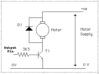
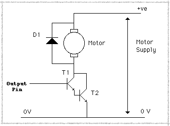
There are two basic ways in which you can power a motor in a single direction, you can have a common earth or a common supply. The only difference is whether a logic 1 turns the motor on or off. These two ways are shown in figure III.

Notice that across each motor there is a diode. This is because when you get the collapsing magnetic fields associated with motors there is a backwards voltage generated. This is called "the back EMF" (Electro Motive Force), the diode effectively shorts this out. I have shown the two different ways in figure III but you can use the same way on each buffer in your circuit. Now look at the table in figure III and you will see we have a number of different options. In the simplest system you can wire the enable input to 5 volts and simply control each motor from one of the digital output pins. You can even use one of the PWM pins on the Arduino to regulate the speed of the motor. This works by rapidly turning the motor on and of and the ratio of on time to off time determines the power you are feeding to the motor. This configuration will also give you flywheel breaking control of the motors.
Flywheel braking is the effect we get when we do not simply deprive a motor of power but short it out as well. If we simply remove the power then the kinetic energy in the rotor and shaft of the motor keep it going. What we have is, in effect, a generator. This produces a voltage in the same direction as that used to make the motor turn. However if we short circuit that voltage then the kinetic energy is quickly drained into the short circuit. Therefore when we do this the motor stops quickly.
If we do not want this effect of rapid motor stopping we can use the enable line to turn the motor off. However in that case you will have to turn both motors off at once.
In order to control the direction of a motor we need to be able to change the direction of current flow through it. To do this we need to use two buffers as shown in figure IV this is sometimes called a H-Bridge, you can see why from the way it is drawn.

Forgetting the enable for a moment we have two control inputs, if they are different the motor is on and if they are the same the motor is off. Here the diode arrangement is a little more complex as we can't swap the diode connections at the same time. Note that here, unlike the single direction case, the diodes that are forward biased are passing the full motor current. Therefore the diodes have to be able to pass as much current as the motor needs.
If we want to control the speed of this then the simplest arrangement is to apply the PWM signal to the enable line. However, you can PWM the signal line if you want but this is a little complex. Say, for example, you are PWMing pin 10 and using pin 15 as a direction control. When you are going clockwise (a zero on pin 15) then a logic one on the PWM signal will turn the motor on, therefor the numbers you send to the analogWrite() function should use to control the speed are normal, the bigger the number the faster it goes. Now when you are going clockwise you have the reverse situation; pin 15 has a logic one and a logic zero on the PWM signal (pin 10) will turn it on, therefore you need to use the inverse of the numbers you used in the other direction. That is easily generated, if the value of the number that sets the speed is in N then the inverse of the number will be:- 255 -N.
With four buffers in the LM18293 you can control four motors in a single direction or two motors bi-directionally. With PWM on the enable line you can control the speed of all the motors.
Isolation
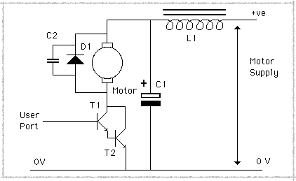
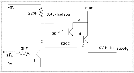
Before we go, just a word about power supplies and motors. Generally motors can be electrically very noisy. This obviously depends on the type of motor but as a rule of thumb the less you paid for it the noisier it will be. If you power a motor from the computer's power supply, this noise can get back into the power lines and crash your computer. No permanent damage will occur but you will find it very frustrating if the computer crashes every time it turns on a motor. If this happens then the first thing to do is to power the motor from a separate power supply. Then if you still have trouble, you can try placing 0.1uF capacitors across the motor. In the unlikely event that you still get trouble you will need to isolate the power supply from the computer as, even though it is a separate one, it is still connected to the computer by the common zero volts or earth line. This can be done by using an opto-isolator. The point to remember is, only go to these measures IF you have trouble.
So armed with these techniques you can make your models come to life, control them through your computer and generally have fun.
More from Mike Cook's Workshop!