GM-TBI-220
Installing New Fuel Injectors in GM Throttle Body Injection model 220
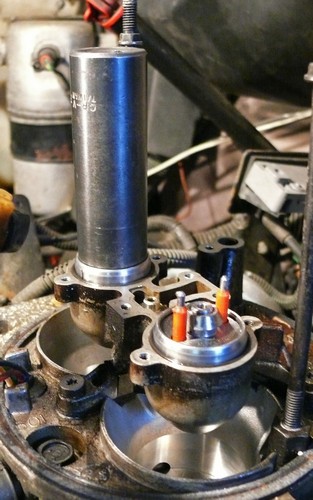
Here's where we started:

- Air Cleaner removed
- Injector connectors disconnected (Squeeze tabs and pull upward).
- Injector connectors wired back out of the way
- Yellow parts box in place (right) to hold small parts
Notice the injector electrical pins are oriented in a line side to side of vehicle. Some later photos show them oriented wrong until I figured out how they really went in. :-)

OK, look closely at the Red numbers on the next photo. The screws 1 to 5 are short and the screws 6 to 8 are long.

Removing the Fuel Metering Cover
You need a #20 TORX driver to remove the screws. I suggest you loosen them all 1/2 turn to start, then evenly another turn, then another. The Fuel Metering Cover you are removing should not be stressed or bent.
Now remove all the screws and put them carefully aside. Reach over the end of the cover towards the firewall, and pull up and down. You should be able to remove the cover without a lot of force. In the photo, the gasket is broken, which should be expected and you will need a new one. On the lower left is a small fuel passage gasket you will also replace.
Removing the Injectors
 The injectors are held in place now by their two o-rings. You can pull them upward by carefully prying with a large screwdriver and some block or other tool to pry against. It should not take very much force. When the injectors come loose about 1/4 of an inch, stop prying.
Notice the orientation of the injector electrical pins: lined up with each other. You will learn how to position them correctly later (And not install them wrong first, like I did).
In the next photo you can see the injectors are loose and their o-rings have been released from their cavity. Pull them up by hand, making sure you

don't drop o-rings down onto the throttle butterfly valves. The injector shown here, as removed, has the large upper o-ring and the small lower o-ring in place
.
Check the cavity the large o-rings were in. Some vehicles have a small metal ring below the o-ring. If so, carefully remove those. You don't want to have to go fishing in the throttle body for them. Like me.
Cleaning things up
You will likely have pieces of broken gaskets on both the removed cover and on the throttle body. You need to carefully remove the gasket pieces and make sure the metal surfaces are clean and flat. A single-edged razor blade or sharp scraper may work. Be careful not to gouge the metal surfaces. See the following photos:


Ready for New Parts
 You may get a kit with two new/reconditioned injectors and necessary o-rings and gaskets as shown in the photo. If not you'll need to get the gaskets and o-rings separately. Note the small "8" shaped gasket for the fuel passage. It's already in place in the photo above. Note the metal support rings that go below the o-rings in the throttle body cavities in some cases.


Ready to install new injectors
Get the injectors ready. Put a little transmission fluid or engine oil on the small o-rings and push them all the way on, up against the final fuel filter.
Orientation Pins!
Do what I say, not what I did :-) NOTICE that the injectors have a small locating pin on their lower edge. (See the Red "O" on the injector photo). The injector has also been marked with a black marker to show the pin location even when the injector is being installed.
Orientation Slots in the Throttle Body !
See the photo above of the throttle body above. The metal support rings have been placed in the throttle body cavities. The large o-rings have had some transmission fluid or oil applied and they have been pushed in place. They may seem difficult to get in place and appear a little too big, but you can hold them in place and push around the circle and fit them in.
  NOTICE that the throttle body casting has a small slot in each cavity to orient the injectors. See the Red "O"s in the photo.
- The driver's side cavity has the slot towards the firewall.
- The passenger's side cavity has the slot towards the radiator.
 Put the Injectors in place

Some downward force will be needed to press the injectors into position. To get an even downward force, I found that a long 3/4 inch 6 point socket fit perfectly over the injector pins and against the injector metal body.
  Use the black mark you made on the upper side of the injector to orient it so that the locating pin will engage the correct slot. You may be able to first press the injector down and rotate it slightly to confirm it is in position, then press down firmly to seat it. It may or may not "pop" into place. Check that both injectors are down at the same level.

Reinstall the cover
Put the new gasket in position on the throttle body. Make sure the small "8" shaped gasket has been put in place on the cover. Alight the cover and place it down into position. Press it down. It should almost have complete contact with the gasket. If it is up 1/8 inch or more, one of the injectors is not down in position. NOTE! The injectors in the photo are oriented WRONGLY! The following photo shows the correct orientation.
When installing screws, do this:
- Put a small drop of Locktite 261 or other medium strength thread locker on the end of the screw
- Push each screw into place and rotate it Counter Clockwise until it "clicks". This means it is in position to start going in Clock Wise .
- Start with Long screw #6. Check that the "8" shaped gasket is in the correct position.
- Insert the rest of the screws. Turn each screw into place most of the way with your fingers. This assures it is not cross-threaded.
- Get all the screws in place with none tight yet.
- Tighten screws with the driver just until they contact the cover.
- Tighten the screws slowly, 1/2 turn at a time in the pattern 7-8-1, 6, 2-5, 3-4 like torqueing a head.
- Tighten in that sequence so they feel evenly tight, and increase up to 28 INCH pounds. If you can't measure torque, I think that's "moderately tight with one hand just reaching forward." Maybe.
Reconnect the electrical connectors
Remove the wire, string etc. that is holding the connectors out of the way. Note: Each connector has a rubber insert that protects the terminals from moisture and dirt. Make sure those are in place, and press them down until they click in place.
Possible Superstition: I remove and reconnect reach connector 4 times to make good contact and minimize any oxidation that may be on the pins or connector.
Reconnect the battery if you disconnected it. Get in the vehicle and turn the ignition key to ON and wait about 5 seconds. You should hear the fuel pump cycle and stop. Turn the key OFF and get out and check for leaks. Do this 3 times.
OK? Start the engine, get out and look at the injectors spraying into the throttle body. Get a good light. The sprays should both be even. Rev the engine by turning the throttle manually. You should see a nice even spray from each injector.
OK? Reinstall the Air Filter and Road Test!
Questions, comments, critiques appreciated! terry at terryking.us
Problem Symptoms of my 1992 GMC Yukon 5.7L V8 VIN K:
This is what lead me to replace the injectors:
- Periodic miss / stumble at idle
- OK when cold: strong at heavy throttle, no missing
- Bad when hot, especially when heat soaked at a couple of traffic lights on warm days:
- Bad missing / rough running at more than 1/3 throttle
- Worst from 1500-2500 rpm, a little smoother above 3000 rpm
- Really bad towing my 3000 pound camper!
- "Injector cleaner" in fuel did not fix it.
NOW it's SO much better!
How the TBI System Works:
The GM designers envisioned a system that would combine the precise fuel control of injection with the simple reliability and lower manufacturing cost of a carburetor. They believed that if the fuel was atomized into a venturi with an injector, instead of being broken apart by a booster as in a carburetor, they could achieve their goal. And so, the hybrid EFI/carburetor was born.

  Locating the fuel injector in the atmosphere above the venturi and throttle plate kept this key component far from the heat that caused injector-fouling issues on the various imported cars and some US Multi-port injection systems. The Rochester TBI injector was virtually impervious to any fouling and would soldier on with the reliability of an anvil. Many have run fine for 150,000 miles with no service. In addition, instead of the high fuel pressure required for port fuel injection to break the fuel apart so that vapor phase change could occur, the TBI design could operate at a low pressure of 9 to 13 PSI--not much more than the 7 to 9 PSI a carburetor needed. This meant the electric, constant volume in-tank fuel pump could run cooler and be less costly and more reliable, since it did not have to work as hard.

  Another benefit was having the fuel injector spray into atmospheric pressure so it didn't have to reference engine vacuum to the fuel pressure regulator. The design was simple and much less complicated than even a carburetor. That was on the mechanical side. The electronic portion of the system was more advanced than the engine controller used with the previous feedback carburetor design, but less complex than the controller required for a port EFI design.
Operating Details:
In a Rochester TBI system, the throttle body is located centrally on the intake manifold in the same position as earlier carburetors and consists of two major components:
- A Throttle Body Injection assembly with either one or two throttle valves that are mechanically connected to the accelerator pedal in the vehicle.
- A fuel meter body assembly with an integral fuel pressure regulator and either one or two electrically actuated fuel injectors.
Other parts of the TBI system include a throttle position sensor, idle control assembly and the body casting itself.
The system also supplies vacuum ports either above or below the throttle plate to operate emission control systems or other accessories.
The amount of fuel delivered by the injection system is determined by the electronic control module (ECM or 'the computer'), and is based on data input from engine sensors that monitor coolant temperature, throttle angle, engine vacuum and ignition timing. A single-wire oxygen sensor monitors the mixture strength. It sends data to the control module for alteration if needed to maintain the ideal 14.7:1 fuel/air ratio.
Fuel is supplied at the rate of 2.5 to 3.44 pounds per minute, depending on the engine, from a constant flow, in-tank electric fuel pump. That fuel is directed to the lower end of the injector assembly, which has a fine screen filter surrounding the injector inlet.
The control module activates the injector solenoid, which lifts a normally closed ball valve off its seat, allowing the fuel under pressure to be injected in a conical spray pattern at the walls of the throttle bore, above the throttle plate. Since the fuel pressure is kept constant by the regulator, the amount of fuel delivered is controlled by varying the length of time (Pulse Width) the injector is held open. Fuel in excess of the injector's needs is returned through a separate line to the fuel tank.
Accuracy of the fuel supply is enhanced by the fuel pressure regulator, which is set at the factory. The fuel pressure regulator is integrated with the fuel cover assembly; it contains an air chamber and a fuel chamber that are separated by a diaphragm-operated relief valve and a calibrated spring. Fuel pressure is regulated by the difference between the fuel pump pressure acting on one side of the diaphragm and the force of the calibrated spring acting on the other side. If the fuel pressure is below specification, the calibrated regulator spring forces the diaphragm and relief valve assembly up toward an opening in the passage, effectively reducing the fuel flow to the return line, allowing fuel inlet pressure to build. When the inlet pressure is sufficient, the diaphragm is forced away from the seat of the opening, allowing fuel into the return line and causing a drop in inlet pressure. The regulator spring, under reduced pressure, expands and forces the diaphragm toward the opening and the process is repeated in a continuous cycle.
The fuel pressure of the system depends on the regulator spring and its calibration. The spring compression is set to maintain fuel flow with a pressure of 9 to 13 PSI. The pressure of air under the air cleaner, acting on the spring side of the diaphragm, changes fuel inlet pressure to compensate for changes in barometric pressure and altitude.
The fuel injector is an electromagnetic device that has a solenoid (electromagnet) which is a multi-layer coil of fine enamelled copper wire. Upon receiving an electrical signal, the plunger or core piece (located in the center of the solenoid winding) is pulled upward, allowing the spring-loaded ball valve to come off the valve seat, permitting fuel flow through a 10-micron screen filter to the spray nozzle.
When energized, on the beginning of each pulse sent by the ECM, the injector has the full system voltage (12 to 14 volts) applied to the solenoid coil. The current starts rising until it reaches four amperes. At this point the plunger should be fully in position. Current regulation then takes over, maintaining a hold current of one ampere which keeps the plunger fully open until the injector is turned off. This allows a fast pull-in of the solenoid armature during turn-on followed by a low energy holding state, which prevents the solenoid coil from overheating.
The standard 120 TBI injectors have a normal solenoid coil resistance of 2.1 ohms. If there was no current regulation taking place, the current would rise to I=E/R so Current = 12/2.1 or about 6 amps. The power dissipation would be P=E*I so Power = 12 * 6 = 72 watts. Too much!
At the system pressure of 9 to 13 PSI, vapor bubbles will be present when fuel temperature is above 100 degrees Fahrenheit. If vapor, instead of fuel, were to be delivered to the injector, fuel metering would be disturbed and the mixture delivered to the engine would be leaner than desired. Since TBI operates in this temperature range, it must be able to handle hot fuel mixed with vapor. To meter the fuel only, a method of vapor separation had to be developed.
To eliminate vapor delivery, the fuel passage to the metering tip of the injector is designed to offer little resistance to the low-velocity fuel. Because of its buoyancy, any vapor present rises into the chamber surrounding the injector metering tip, so that only fuel is available when the injector is turned on. Incoming fuel flow in excess of injector needs, after passing the metering passage, enters the fuel pressure regulator, then passes back into the fuel return line and back to the tank. This allows stagnant vapor to be purged from the system. The fuel return line is large enough to prevent back pressure buildup and allows proper regulation.
Credits: I started with a text file I got "somewhere?" a couple years ago and rewrote some and added some. If anyone can spot the origin I will credit it here.
zz