Insert-Text-Test
Test of inserting plain text in WikiSpace Page 4/24/15
This is a copy of an existing page for test purposes. 3 lines of plain text will inserted near the end.
Robot 7-way Multi Tracking Sensor
![]()
This sensor is designed for "Line Following" autonomous vehicles (AKA Robots), but it may have other purposes as well. You can Find it HERE. Here's a Video of it following a complex path:
Features:
- 4 line-tracking sensors spaced out horizontally
- 1 centered tracking sensor optimized for crossing lines
- 1 pair of emitter-detector aimed forward for collision avoidance, with sensitivity adjust
- 1 micro-switch for use with mechanical bumpers
- LED Indicators on every sensor
- Active LS14 chip providing clean hysteresis on each sensor for jitter-free indication
- Detection distance of 0-4 cm (black and white line sensor) )
- Input voltage :3.0-5 .5 V
- digital output (Active HIGH for detected light object, bump switch)
- About 5.4 inches across
Connections: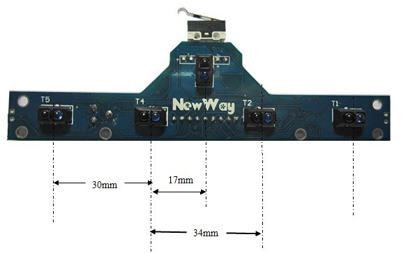
VCC5 + 5 Volts DC Power
GND -- Ground
SS1, SS2 -- Leftmost two downward-looking sensors (T1 and T2 in photo, right)
SS3 -- Center Sensor, optimized for seeing horizontal lines that are crossed if moving ahead.
SS4,5 -- The next 2 Sensors on the right (top view) and T4 and T5 in photo, right)
Near -- The Forward-looking IR LED and Sensor on separate wires. NOTE: aim them to converge 1 to 2 inches ahead. They are just held by their leads, and you may want to create some "Front Panel" on your robot with a couple of holes for these to fit through.
CLP -- The Micro-switch on the front, usually used as a physical "bump" sensor.
![]()
Connections:
On the right you can see how we used the CableMaker flat cable and Pin Strips to make a neat secure connection between a YourDuinoRobo1 and the 7-way sensor.
Line Tracking:
A contrasting line / stripe is placed on a floor (Such as a black stripe on a light colored floor). The Robot starts out on the line and moves forward. The sensors
- Immediately after PASTE, the screen jumps here to the center of the page
change state when a line is almost directly under them. ![]() The Robot's intelligent software looks at the sensor's output and decides whether to travel straight, or turn left or right to follow the line.
The Robot's intelligent software looks at the sensor's output and decides whether to travel straight, or turn left or right to follow the line.
This device has 5 downward-looking sensors, and so the software can see whether the robot is on the line, off a little left or right, or off more, left or right, and drive to follow the line.. See the Video link above! As you can see, the outer sensors can also tell when a line crosses the line the Robot is following. Then software can decide whether to follow that new line or not. It also can tell when it gets to a "Tee" at the end of a line. In the Video it also bumps into the panel at the "Targets" to prove it got there, and then turns around..
The overall Robot software can be very complicated if it is well done. But first, what would some simple Arduino Software Sketch be like??
Simple 7-way sensor Test:
This Software Sketch uses the 7-way sensor connected to pins 2,4,7,8,11,12 (saving most Servo outputs for a Robot, later).
  NOTE: The "analog" pins 1 to 6 can also be used as digital inputs. If you have the YourDuino Basic Robot Kit, you might use those pins for the Line Follower Sensor. You will see two main "Functions" near the end. getSensorData does a "digitalRead" of each of SS1 thru SS5 and "Bump" and the forward-looking "Near"on the sensor. showSensor Data sends lines of text to the Serial Monitor that show the states of the sensors. They are shown in order from SS1 thru SS5, from Left to Right of the sensor. Far right is shown as "R" and near left is shown as "r" etc.
  So it will look like this if the Center sensor sees a light-colored line: --C-- and like this if it is a little off to the left: ---l-
  Cut and paste this code into an Arduino IDE window.

  The Sketch Output looks like this:

  (Centered)
  Test Start
  - - C - - END

  (Off to right)
  Test Start
  - - - r - END

  (Tee to the left:)
  Test Start
  L l C - - END
INSERT POINT:
Here are several lines of plain text that will be copied and pasted into the main document that has plain text except for the H1 top title.
Here are several lines of plain text that will be copied and pasted into the main document that has plain text except for the H1 top title.
Here are several lines of plain text that will be copied and pasted into the main document that has plain text except for the H1 top title.
Line following Algorithm?
Now someone just needs to write a function that takes this data and outputs Left and Right Motor speeds from -100 (full reverse), to 0 (stop), to 100 (full forward) and follows a line. Dynamic control based on amount of error would be nice, maybe even PID. See the Video above to get an idea of what is needed.
Checking Infrared Sensors:
Humans can't see the Infrared (Redder than Red) beams from this sensor. But your digital camera can! Looking through your viewfinder, you can even see them blink. Here's an example:


  zz