LowCostStarterSet-Circuits-Switches
CIRCUITS AND SWITCHES
CIRCUITS are what it's all about: The DNA of Electronics.
CIRCUIT DIAGRAMS (W) are how most electronics people keep their head together about electronics.
Circuit Diagrams use SYMBOLS(W) to represent electronics parts.
EVERYTHING IS ABOUT SWITCHING :
Let's look at this picture:
external image Yourduino-Inputs1.jpg
YOU switch INPUTS to HIGH or LOW (1 or 0)
ARDUINO switches OUTPUTS to HIGH or LOW (1 or 0)
Think about that:
- The things YOU wire up (like switches, thermostats, light sensors) switch INPUTS to HIGH or LOW (1 or 0)
- ARDUINO switches OUTPUTS to HIGH or LOW (1 or 0)
BUT: How does Arduino KNOW when to switch outputs? YOU tell it by writing software called "Sketches".
If you're just beginning with this stuff, it's difficult to relate Circuit Diagrams to the real physical electronics you have you hands on. Slow down and follow along and it will become much clearer.
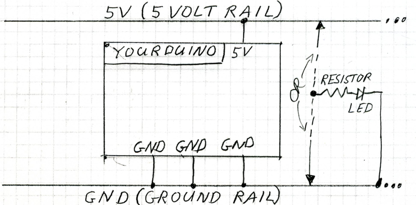
We're going to go back to our diagram of Arduino and the "Rails":
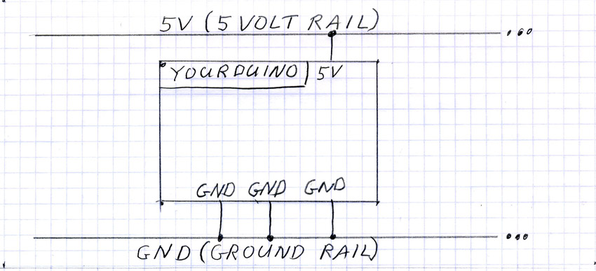
We will add devices to this and show you how to make them work:
- Single-bit OUTPUT DEVICES like LEDs and beepers
- Single-bit INPUT DEVICES like pushbutton switches and light sensors
- Complex devices that send and receive SIGNALS to operate, like temperature sensors and servos.
Blank copies of this diagram in a PDF file are here:
- [/file/detail/YourDuinoDiagram3Blanks.pdf Details]
- [/file/view/YourDuinoDiagram3Blanks.pdf/294459398/YourDuinoDiagram3Blanks.pdf Download]
- 499 KB
. You could print some for your first diagrams.
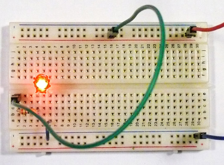
  The photos here show connections made with a "Solderless Breadboard". For a while we'll keep the layout of our physical Breadboard similar to the symbolic diagram above.

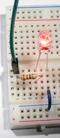
  On the left is better detail of the way the Resistor (220 ohms: red-red-black) and the LED (+ long lead to the left) are inserted into the breadboard. SO: Make your breadboard look like the photo, now... And plug in your Arduino which will provide 5 V power on the Red (5V) and Blue (GND) wires. The LED should light up. Why??
  The "LED Circuit" is: GreenWire -> Resistor -> LED+ and LED- -> GND. Here's what 's happening:

  The Green wire from the resistor-LED circuit can be connected to the Red Top High +5V Rail, or to the Blue Bottom - Low GND rail. Do it: Plug the wire to the Red 5V rail. The LED lights up. Plug the wire to the Blue GND rail. The LED is out. Repeat this, changing once every 1 second for several times: 5V rail, GND Rail.

 You're about to be out of a job! Because what you're doing is exactly what Arduino does with Digital Outputs: it switches them to either the 5V Rail or the GND Rail.

  Now plug the wire into socket 13 of YourDuino. If you have the GOBP (Good Old Blink Program) running, the LED will be switched back and forth from the 5V Rail to the GND Rail. You can take a break. And, as we saw earlier, it can switch Wicked Fast!
  In a minute we will hook up several of the Yourduino I/O pins to our breadboard, and then try out both INPUT and OUTPUT devices.
  But, which pins can we use for INPUTS and OUTPUTS? Fortunately YourDuino's answer is, "YOU Decide!". Every I/O pin can be used as either an INPUT or an OUTPUT.
  Let's wire up more pins and then we can do some more interesting stuff.
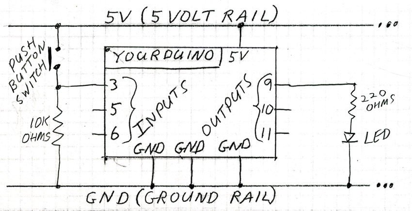
Here's our new picture. The difference is we show multiple pins for INPUT and OUTPUT. NOTE: YourDuinoRobo1 has 20 pins that can be used for Digital Inputs and Digital Outputs. The Good News is that ANY of the pins can be used as either Input or Output. You decide in your Software Sketch in the (beginning). YourDuinoRobo1 brings 6 of those pins out on the upper set of pins (along with 5V and Ground for every one, and another 6 pins out on the lower set. The diagram above just shows the connections to the upper 6 , and for now we'll use them for Inputs and Outputs as shown.
Look at the next two photos and get out your flat multicolor cable and pin strips. Here's a look at how we will keep the Breadboard organized even with multiple Inputs and Outputs being used. Break off sections of a pin strip as shown (1, 2 and 3-wide pieces), and a 6-wire section of the flat cable.
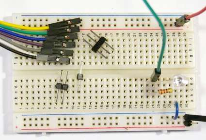
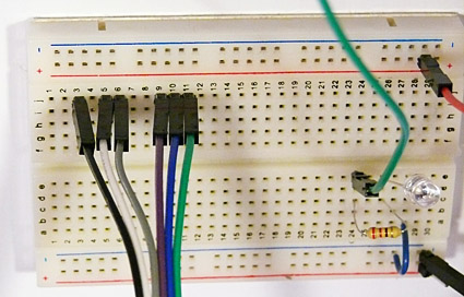
Since we are going to use Arduino pins 3,5,6,9,10,and 11, push the pin strip sections into the breadboard next to those numbers, and then plug the cable onto them. The other end of the cable will go to the YourDuino as shown in the following photos. NOTE: You need to make a 1/2 twist in the cable so the same color goes to the same number pins.
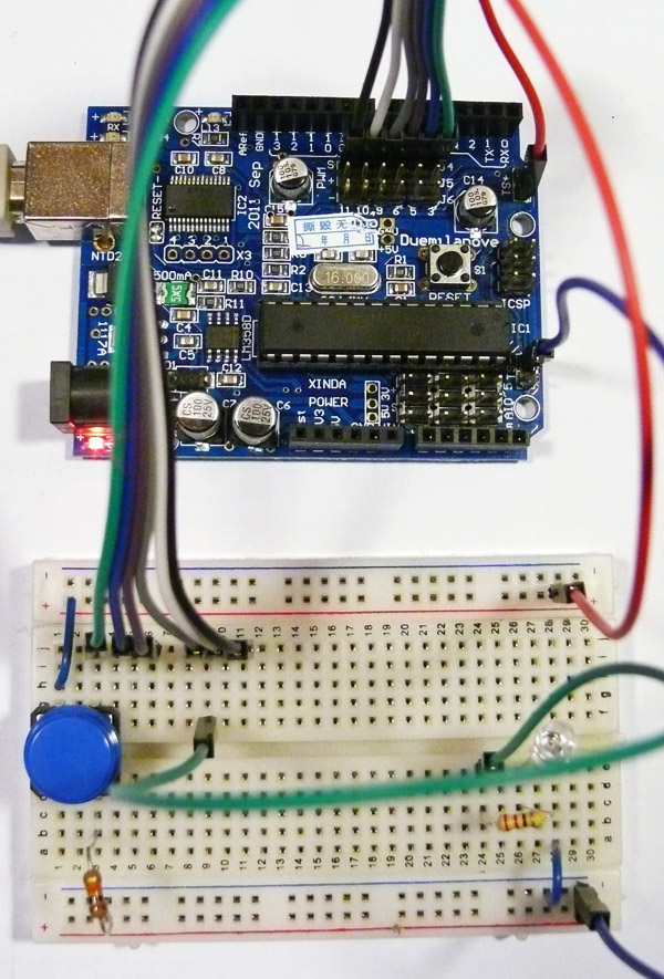
We've rearranged the Breadboard (right) a little to move the LED to the right as shown and added the pushbutton switch and resistor that you can see on the left of the diagram above. Let's look Closely Now. 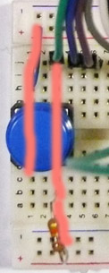
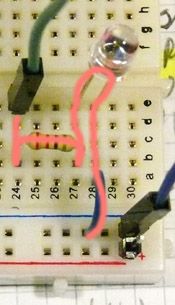
We are going to make the physical circuits that are shown as symbols on the schematic diagram above. The pink traces show the Circuit Path. Trace them. Remember the vertical rows of 5 pins in the breadboard are all connected together.
Left: +5V Rail -> left side of Switch - Right side of Switch -> up to Pin 3 and down to 10K resistor to GND Rail.
Right: Pin 9 -> left side 200 ohm resistor - right side 200 ohm resistor -> LED+ (long pin on LED) LED- -> down to blue wire to GND Rail.
This is difficult at the beginning! The abstract symbols on the Schematic Diagram are made real by the physical components and the breadboard connections. You'll get used to it if you Trace each circuit.
OK, we have a switch on the left side, connected to an Arduino input on Pin 3.
And we have our LED connected to an Arduino output on pin 9.
