LowCostStarterSet-Connecting-Breadboarding
CONNECTING AND BREADBOARDING
BREADBOARDS, WIRES, PINS, CABLE and ELECTRONICS COMPONENTS:
Arduino is great but sometimes connecting interesting things to it can be a pain. We have done a lot to try to make it easier for you. [/Cables See the section here:] "Electronic Bricks" are easiest to connect, but more expensive. With this kit we will use a BREADBOARD (W) for most connections. [NOTE: The (W) Means this is a Wikipedia link.]
The idea here is that wires and electronics parts like LEDs and RESISTORs can be plugged into the BREADBOARD and then easily be removed or changed. The holes in the BREADBOARD go down into little sockets with metal contacts.
Sections of the BREADBOARD have rows or columns that are all connected together, making it easy to have multiple things connected together.
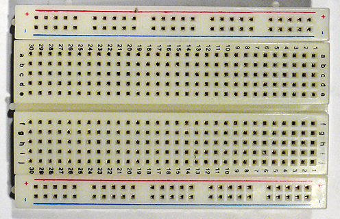
Here's some detail of how the BREADBOARD that we use in this kit is organized:
external image BreadBoard-1.jpg
The Horizontal Rows have 5 holes (abcde) and (fghij) with sockets that are connected together. Any wires or parts that are plugged into this row are connected together.
The Vertical Columns (+Red and -Blue) have the same connection running all the way down. We will use these to connect 5V on our YourDuino board to the +Red and to connect GND on our YourDuino board to -Blue. Then any time we need to connect to GND, we just plug a wire or part into the -Blue column, and any time we need to connect to 5V, we just plug a wire or part into the +Red column.
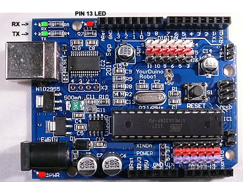 Now let's look again at the YourDuinoRobo1 board and where we will make connections there. Later we will look at the board in a lot more details, but for now let's just hook up a few things and make then work.
First thing we want to do is connect GND on the board to a -Blue column on the breadboard and 5V on the board to a +Red column.
We will orient the breadboard left-to-right so it can sit in front of the YourDuino board so we can easily make many connections and changes.
 So it will look something like this:
We will mainly use the upper +Red row and the bottom -Blue row. Often we think of these parallel lines as "Rails" like railroad rails. The top red rail is the "+5 Volt Rail" and the bottom blue rail is the "Ground Rail". "Voltage Rails" (Wikipedia) is a common terminology in electronics.
What about wires? Locate the "40 pin flat cable" and the "Male-Male Pin Connectors" in your kit.
So to start we will connect the "5V Rail" to "5V" on the YourDuino board.
WIRES:
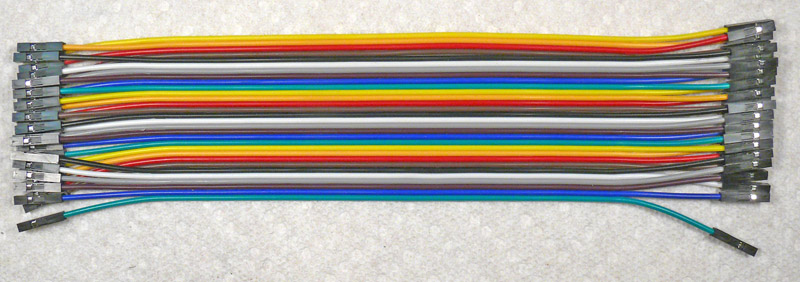
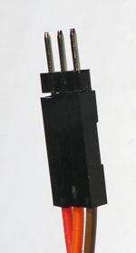
We will use the "40 pin flat cable" in your kit for wires. It looks like this:


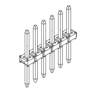
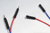
  You can easily strip off one or more wires, or strip off a section to use as a cable. The ends of these wires are female connectors that can plug onto the connectors on the Robo1 or a "Sensor Shield". But what about the breadboard?? It needs a wire with a male end to plug into it. Here (right) is the answer. Your kit has 2 of these with 40 pins each. You can cut or snap off the number of pins you need. For now, snap/cut off about 6 single pins.
Here's the way this works:
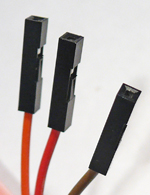
| female wire ends |
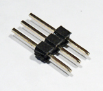
| 3-pin strip |
| 3-pin cable end |
| male pins (left) |
You can make any combination of male or female cable ends of different widths.
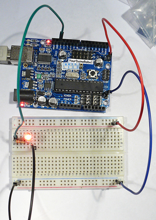 Now, let's connect your Breadboard to the YourDuino board:
A Red wire runs from a +5 pin on the YourDuino to the +Red Rail on the breadboard. A Blue wire runs from a GND pin on the YourDuino to the -Blue Rail on the breadboard. Now it's easy to connect things to the 5V (+Red) Rail or the GND (-Blue) Rail.
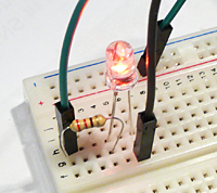 See the close-up photo here, and plug a 220 Ohm (Red-Red-Brown) resistor and a red LED (Long pin to the left) into the Breadboard as shown. Now add a wire (Black is shown) from the same vertical strip as the LED to the GND Rail. Connect another wire (Green is shown) to the same vertical strip as the left end of the resistor, and use a pin to plug it into the YourDuino socket labelled 13. (Use male-male pins where you need a male end to plug into the breadboard or YourDuino)
Time to Power Up! Plug the USB cable from your computer into the YourDuino. Its PWR LED should come on. And the pin 13 LED should be blinking in the way you last programmed it. If necessary load the original GOBP (Good Old Blink Program!) and Upload it to YourDuino. Your setup should look like the photo on the right above. AND the LED you just wired up on your Breadboard should blink the same as the 13 LED on YourDuino. NO? Recheck that you have it wired like the photos, and the the LED's longer lead is to the left.
Let's figure out what's really happening here. Unplug the wire from YourDuino pin 13 (keep the pin with it). Now try two things:
- Plug the free end of the wire into the +5V Rail. It should light up.
- Plug the free end of the wire into the GND Rail. It should be off.
Try it a few times, like 1 second to +, 1 second to GND. Now plug it back into YourDuino Pin 13. I should blink again.
What's happening here?? The YourDuino is doing exactly the same thing automatically that you did manually! It is connecting the circuit connected to pin 13 to the +5V Rail and then connecting it to the GND Rail.
That's how "Digital Outputs work.
OK, you have a good beginning in setting up YourDuino, Programming it, and wiring up external devices.
Now, let's slow down a bit. In our next section, we'll think about what's going on here, which is CIRCUITS.
And what's all this stuff about PINS , BITS , ONES and ZEROS , HIGH and LOW... ? ?
In the next section:
PINS...
BITS...
ONES and ZEROS...
HIGH and LOW...
... YOU'LL KNOW!!
[/StarterSet-Circuits-Pins-Bits (GO THERE)]
