NRF24L01-Mirf-Examples
Mirf Library: nRF24L01 Test
See the Arduino Playground page about the Mirf library:
http://www.arduino.cc/playground/InterfacingWithHardware/Nrf24L01
Here's an example of using the Mirf library. It's basically an implementation of transmitting information from one Arduino moving around the environment (the "sensor") to a stationary base station. For simplicity, they opted for the following approach:
- The data is transmitted from the sensor in the form of simple ASCII strings.
- Each character of the ASCII is transmitted indiviually (very inefficient, but really simple).
- The base station just pipes the received data via the serial port to the PC.
- The PC is running software (for example based on Processing) which reads, error-checks and displays the received data.
Thus, it is a kind of a very simple "wireless serial link" between a sensor (transmitting only) and a base station (receiving only).
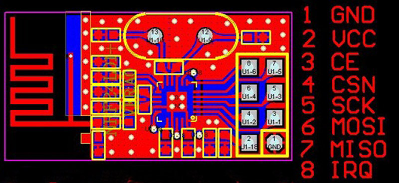
Here's the pinout of the Modules we have (TOP VIEW):

Here's the code for the base station. The code simply pushes every character value it receives from the nRF24L01 to the serial port. It's up to the PC-program to error-check and analyze what is received.
Code:
#include <Spi.h>
#include <mirf.h>

void setup()
{
  Serial.begin(57600);

  Mirf.init();

  // name the receiving channel - must match tranmitter setting!
  Mirf.setRADDR((byte *)"TX_01");

  // just a single byte is transmitted
  Mirf.payload = 1;

  // we use channel 90 as it is outside of WLAN bands
  // or channels used by wireless surveillance cameras
  Mirf.channel = 90;

  // now config the device....
  Mirf.config();

  // Set 1MHz data rate - this increases the range slightly
  Mirf.configRegister(RF_SETUP,0x06);
}

void loop()
{

  byte c;

  // is there any data pending?
  if( Mirf.dataReady() )
  {
     // well, get it
     Mirf.getData(&c);

    // ... and write it out to the PC
     Serial.print(c);
  }
}
Sensor:
 #include <Spi.h>
 #include <mirf.h>

 // converts a float into a char
// and sends it via nRF24L01
void transmit( float v)
{
  byte c;
  char buf[10];

  dtostrf(v,9,3,buf);

  for( int i=0 ; i<8 ; i++ )
  {
    c = buf[i];
    Mirf.send(&c);
    while( Mirf.isSending() ) ;
  }
}

// sends a string via the nRF24L01
void transmit(const char *string)
{
  byte c;

  for( int i=0 ; string[i]!=0x00 ; i++ )
  {
    c = string[i];
    Mirf.send(&c);
    while( Mirf.isSending() ) ;
  }
}

// send a CR/LF sequence via the nRF24L01
void transmitlf(void)
{
  byte c;

  c = '\r';
  Mirf.send(&c);
    while( Mirf.isSending() ) ;

  c = '\n';
  Mirf.send(&c);
    while( Mirf.isSending() ) ;
}

void setup()
{

  // init the transceiver
  Mirf.init();

  // we transmit only a single byte each time
  Mirf.payload = 1;

  // selecting a channel which is not too noisy
  Mirf.channel = 90;
  Mirf.config();

  // Set 1MHz data rate
  Mirf.configRegister(RF_SETUP,0x06);

  // Set address - this one must match the
  // address the receiver is using!
  Mirf.setTADDR((byte *)"TX_01");
}

void loop()
{
  float v01,v02;

  // read in some values
  v01 = analogRead(0);
  v02 = analogRead(1);

  // transmit a fixed token
  transmit(" : ");

  // transmit the first value
  transmit(v01);

  // transmit a separator
  transmit(" : ");

  // transmit a second token
  transmit(v02);

  // transmit a CR/LF for the PC
  // software to sync to
  transmitlf();

  // ... just take your time
  delay(100);
}
The PC software monitors the serial port of the Arduino which is acting as a base station and waits for a CR/LF-sequence to arrive in the data stream in order to start processing.
Once a full string is received, a simple error-checking strategy is employed in the PC software. The first thing to check is whether the two ":" transmitted from the sensor are present.
Furthermore, as the float values are converted by the sensor into strings with a fixed length, the total length of the transmitted string stays constant. However, some bytes might not be received by the base station.
So if you display only data which does have the two ":" transmitted and does have the correct message length, the link becomes quite stable.
As mentioned, this code does not really use any of the advanced features of the nRF24L01, but it should get you started with communications between two Arduinos.
You might want to go further by trying to implement:
- Transmitting directly binary data in larger data chunks. The nRF24L01 can transmit up to 32byte in one piece.
- Fine-tuning the Shockburst mode and other transmission parameters for your needs.
- Implementing a two-communication link.
- Utilzing/taking care of the FIFO in the nRF24L01.
As the nRF24L01 does feature error-checking in Shockburst mode, such an improved implementation will release the burden of error-checking from the analyzing software running on the PC. The above described method is simple and fast (or quick and dirty, depending on the way you look at it
| smiley-wink |
).
NOTE: The 24F Library is much more full-featured and does error checking etc. [/nRF24L01-RF24-Examples See it here:]