PING)))
NOTE: WE also have information about [/UltraSonicDistance another type (4-pins) of Ultrasonic Sensor HERE:]
Table of Contents
What is Ping
The Parallax PING))) ultrasonic distance sensor provides precise, non-contact distance measurements from about 2 cm (0.8 inches) to 3 meters (3.3 yards). It is very easy to connect to BASIC Stamp®, Javelin Stamp, or a Arduino microcontroller, requiring only one I/O pin.
The PING))) sensor works by transmitting an ultrasonic (well above human hearing range) burst and providing an output pulse that corresponds to the time required for the burst echo to return to the sensor. By measuring the echo pulse width the distance to target can easily be calculated.
Specifications
- Supply Voltage- 5VDC
- Supply Current- 30mA to 35mA max
- Range- 2cm to 3m (0.8 in. to 3.3 yrds)
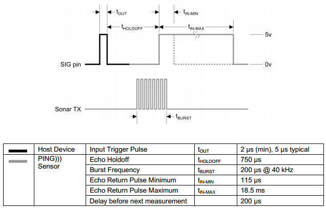
- Input Trigger- positive TTL pulse, 2uS min, 5us typ.
- Echo Pulse- positive TTL pulse, 115 uS to 18.5 ms
- Echo Hold-off- 750 us from fall of Trigger pulse
- Burst Frequency- 40kHz for 200 us
- Burst Indicator LED shows sensor activity
- Delay before next measurement- 200us
- Package: 3-pin SIP, 0.1" spacing (ground, power, and signal)
- Operating temperature: 0 to 70 degrees C.
Dimensions
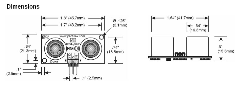
- Size: 22 mm Hight by 46 mm Width by 16mm Diameter (0.84in. x 1.8in. x 0.6in.)
Pins
| GND |
Ground (VSS) |
| 5V |
5 VDC (Vdd) |
| SIG |
Signal (I/O pin |
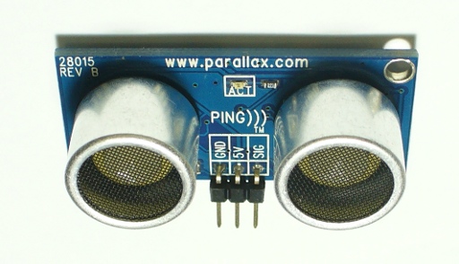
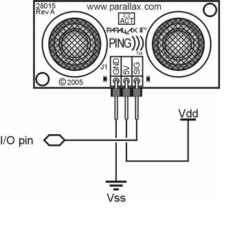
The PING))) sensor has a male 3-pin header used to supply power ( 5 VDC), ground, and signal. The header allows the sensor to be plugged into a solderless breadboard, or to be located remotely through the use of a standard servo extender cable. Standard connections are shown above.
Theory of Operation
The PING))) sensor detects objects by emitting a short ultrasonic burst and then "listens" for the echo. Under control of a host microcontroller (trigger pulse), the sensor emits a short 40 kHz (ultrasonic) burst. This burst travels through the air at about 1130 feet per second, hits an object, and then bounces back to the sensor. The PING))) sensor provides an output pulse to the host that will terminate when the echo is detected, hence the width of this pulse corresponds to the distance to the target.

Example Code
Here some code that use two servos, two LED's, one PING))), one LED, one photoresistor.
This code still needs some work to be done on the code to make it smoother but if you wire every thing up, correctly, it should work. So if you want to you can modify it and add below this code.
#include <Servo.h> includes the servo libs
Servo LeftServo1; name the servo
Servo RightServo2; name the servo
int ultraSoundSignal = 7; Ultrasound signal pin
int val = 0;
int val2 = 0;
int ultrasoundValue = 0;
int timecount = 0; Echo counter
int ledPin = 13; LED connected to digital pin 13
int lightSense = 2;
int headLight = 8;
void setup(){
pinMode(6,OUTPUT);
pinMode(5,OUTPUT);
LeftServo1.attach(6); Attaches the Left Servo to PWM pin 6 on the Arduino
RightServo2.attach(5); Attaches the Right Servo to PWM pin 5 on the Arduino
pinMode(headLight, OUTPUT);
pinMode(lightSense, INPUT);
Serial.begin(9600); Sets the baud rate to 9600
pinMode(ledPin, OUTPUT); Sets the digital pin as output
}
void moveServoLeftTo(int angle, int duration){
command the servo to move to the given angle for the given number of milliseconds
LeftServo1.write(angle);
for (int i=120; i > 0; i = i-20){ loop for the given number of milliseconds by subtracting 20ms each iteratio
}
}
void moveServoRightTo(int angle, int duration){
command the servo to move to the given angle for the given number of milliseconds
RightServo2.write(angle);
for (int i=60; i > 0; i = i-20){ loop for the given number of milliseconds by subtracting 20ms each iteration
}
}
void loop() {
Ping))) functions: Doing more than I need it to, I think, but code
timecount = 0;
val = 0;
pinMode(ultraSoundSignal, OUTPUT); Switch signalpin to output
digitalWrite(ultraSoundSignal, LOW); Send low pulse
delayMicroseconds(2); Wait for 2 microseconds
digitalWrite(ultraSoundSignal, HIGH); Send high pulse
delayMicroseconds(5); Wait for 5 microseconds
digitalWrite(ultraSoundSignal, LOW); Holdoff
pinMode(ultraSoundSignal, INPUT); Switch signalpin to input
val = digitalRead(ultraSoundSignal); Append signal value to val
while(val == LOW) { Loop until pin reads a high value
val = digitalRead(ultraSoundSignal);
}
while(val == HIGH) { Loop until pin reads a high value
val = digitalRead(ultraSoundSignal);
timecount = timecount +1; Count echo pulse time
}
ultrasoundValue = timecount; Append echo pulse time to ultrasoundValue
if(timecount > 0){
digitalWrite(ledPin, HIGH);
}
delay(1);
Servo functions: The basics
if(ultrasoundValue > 500){
moveServoLeftTo(45,50); move the left servo to 45 degrees for 500 milliseconds
moveServoRightTo(180,50); moveRightTo function is left as an excercise ;)
}
if(ultrasoundValue < 500){
moveServoLeftTo(180,40);
moveServoRightTo(180,40);
}
if(ultrasoundValue < 100){
moveServoLeftTo(180,100);
moveServoRightTo(45,100);
moveServoLeftTo(45,50);
moveServoRightTo(180,50);
}
Headlight - Turns on when photoresistor is triggered
Doesn't seem to work on the same circuit... not sure why yet.
/* val2 = digitalRead(lightSense); read input value
if (val == HIGH) { check if the input is HIGH
digitalWrite(headLight, LOW); turn LED OFF
} else {
digitalWrite(headLight, HIGH); // turn LED ON
*/
}
Links
Parallax
Example Code


