RobotKitMenu-5
BUILDING THE ROBOT BASE:
At this point, you should have tested the Servo and Ultrasonic Sensor and have them assembled with the bracket. They're probably still plugged into the RoboRED; you can move all that onto the Robot Base after it is assembled.
Before you start to build your Robot Base, become familiar with all the parts and what they are called. Check that you have all the components in the kit. There is another page that shows all the parts and explains them. If you didn't do so at the beginning, go check that page(HERE) and then return. NOTE: The 4-position battery case and printed sheet that may be inside your parts package will not be used!
HINT: Use an egg carton or small dish when you open the small parts ziplock bag. Organize the parts. (Many of the small bolts and nuts will not be used).
ROBOT CHASSIS, WHEELS and DC MOTORS

- Robot Chassis: Laser-cut clear plastic. This has a stick-on paper covering, and this is a good time to remove it if you want the clear plastic to be shown. (You want at least one side clear for the Velcro to adhere well). This is why we have fingernails :-)
- Wheels (2). The wheels have a hole in the center with two flat sections. Make sure you line this up with the motor shafts later when you attach them.
- DC Gear Reduction Motors (2). These have 2 wires attached. Later, when you assemble them to the chassis, make sure the wires go towards the center of the robot.
Assembling the Robot Base Chassis and Attaching the Parts
First, you will attach these parts to the robot chassis and then connect them electrically:
- Motor Driver Board
- DC Motors
- Yourduino RoboRED
- ServoMotor and Ultrasonic Distance Sensor on Bracket
- Battery Case
CHASSIS:
- Notes on Optional Power Switch: We do not show how to wire the optional power switch; it would require soldering which the kit avoids. If you plan to use the power switch later, line it up with the rectangular hole in the center of the chassis and PUSH it down into position. This may take a strong person with strong fingers, or you may have to file the switch case to make it fit! Many people simply plug and unplug the battery connector to turn the robot on and off. The switch may have a red dot showing the ON position. We suggest you point it toward the front (wide end) of the robot.

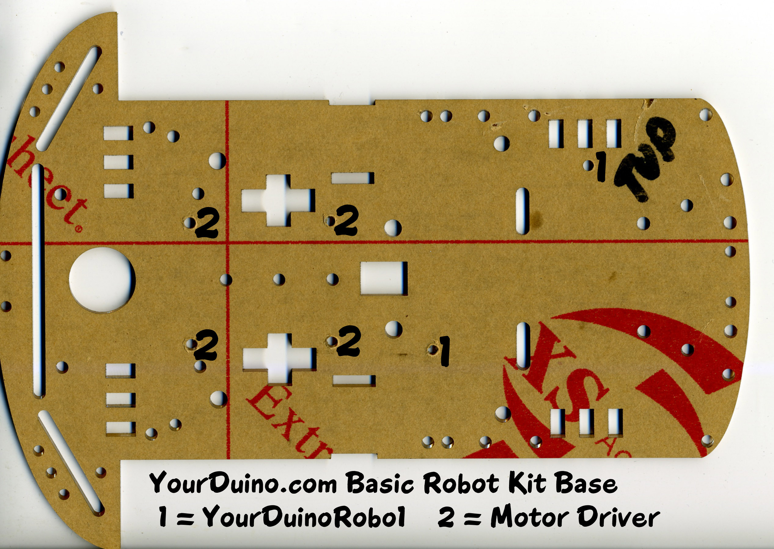
- Originally we supplied a chassis with predrilled boards and "TOP" marked. Younger (and other!) people had difficulty with the small hardware used to attach the RoboRED and Motor Driver. As of September 2015 we supply Velcro-type adhesive strips which are easier to handle and allow things to be removed. It is also better for the battery case which is often removed.
- See the photo for suggested locations for the Velcro sections. We suggest you put the HOOK part on the chassis and the LOOP (fuzzy fabric) part on the RoboRED, Motor Driver, Servo and especially the Battery Case so that it won't snag things when it is not attached..
- IF you want to drill holes in the chassis yourself, a .JPG file that will give you an accurate layout if you print it at 300DPI is available HERE. The holes should be 1/8" (USA) or 4mm (Metric).
- NOTE: Probably better to mount motors before attaching other parts like Motor Driver etc.
- Locate the 4 Motor Mounts. Use 2 at a time to attach each motor to the chassis.
- On the underside of the Robot Chassis, place the motors with their wires facing towards the center of the chassis and towards the back.. close to the edge of the RoboRED locatio.. (NOTE: Velcro is now used for the motor driver and RoboRED, not the screws in this photo!)
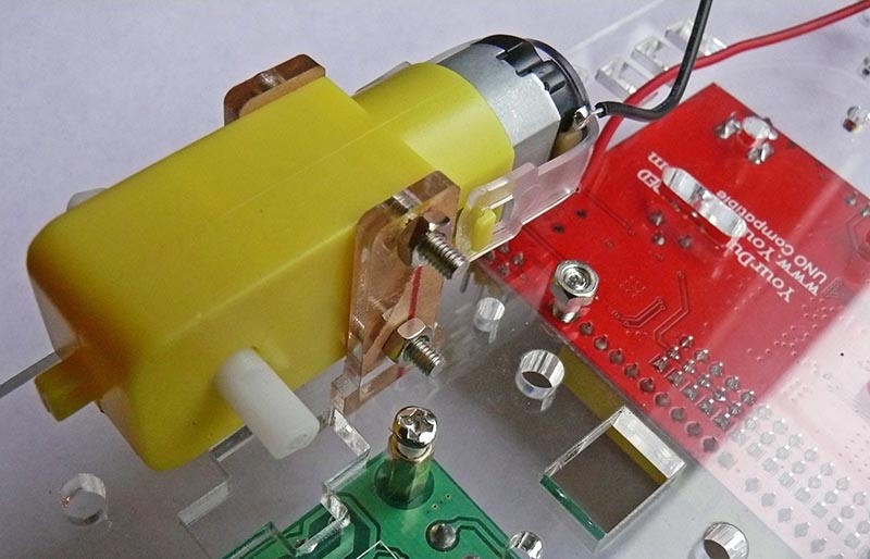 (<- See Photo)
- 1 bracket is inserted up through a center slot and the 2nd bracket goes in a slot on the outer edge of the chassis.
- Turn the chassis over and insert the long machine screws through the outer brackets, through the holes in the motor, and through the inner bracket. HINT: Hold the nuts flat against the motor, with the screws extending out. Rotate the screws until they start onto the nuts. Then spin the nuts in place lightly.

- (See Photo Below)

Attach two nuts and tighten just snug but not too tight. The plastic is not real strong. Hold the lower nut in position as shown and then start and tighten the screw.
- Install the second motor on the other side.
- Route the wires up through the two larger round holes closest to the rectangular cutout in the center of the chassis. (NOTE: Velcro is now used for the motor driver and RoboRED, not the screws in these photos!)

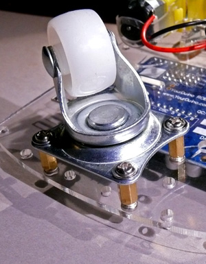 CASTER WHEEL
- At the back of the chassis, check out the position of the holes by placing the caster wheel on the bottom of the chassis, to see which 4 holes line up with the holes on the caster wheel.
- Now, attach the 4 metal 'standoffs' by putting 4, 8mm long machine screws from the top of the chassis, through the 4 holes and into one end of the standoffs. Hold the standoffs and tighten the screws with the small Phillips screwdriver.
- Line the caster wheel holes up with the 4 standoffs and attach it with the 4 small screws that have large flat heads.
- Line the caster wheel holes up with the 4 standoffs and attach it with the 4 small screws that have large flat heads.

(Photo Below) Here is the Robot Chassis with the parts attached (Now we supply, Velcro, not screws). The motor wires are routed through the holes.
We suggest you wait until later to attach the wheels. It's easier to test the wiring and software when the robot can't try to escape :-)

Attach RoboRED and Motor Driver
- RoboRED: Attach the RoboRED to the chassis using Velcro (See photo) NOTE: RecentRoboREDs have a small black jumper which should already be in the 5V position. If you don;'t have that jumper, find the small silver colored switch near the USB connector, labeled 3V3 and 5V. Make sure this switch is pushed to the 5V position. If you have the Servo and Ultrasonic wires connected, put them off to the side temporarily.
- Attach the motor driver as shown using Velcro
Connecting the wires from the RoboRED to the components
Motor Driver Board
The Motor Driver board looks like this: (See Photo)

The motor wires will connect to the blue terminal blocks on the left and right. The RoboRED control wires will connect to the small black terminal strip in the lower center, and the motor power will connect to the bottom blue terminal strip at "VCC" and "GND".

Important note: As received, there are two jumper blocks on the motor driver connected to the ENA and ENB Pins which must be removed. You can pull them straight up off the pins using tweezers or your finger nails. (See Photo )
Now you are going to use wires from the Rainbow cable to connect the RoboRed pins to the corresponding pins on the Motor Driver Board. The connections and corresponding wire colors are shown in the following table. We are using different colored wires to make the wiring easier to understand. This may seem complicated, but if you follow the steps below, it will all come together!
NOTE! The connections shown below are correct. SOME of the photos show White and Black wires reversed. THIS is right. (Sorry!) 

1. Strip off a section from your "Rainbow" flat cable with 6 wires, with colors Green through Black. Push one end of this cable onto the RoboRED pins (Longer Yellow strip) 5-6-7-8-9-10 as shown in the photo. (These numbers may not be printed on the board. Notice the section starts at the 7th position from the right.) They must be on the Yellow (signal) pins, not the Red (Voltage) or Blue (Ground) pins.
2. Connect the other end of the cable you made to the Motor Driver, with each colored wire connecting to the corresponding pin on the motor driver board, as shown in the table above. (See photos)
|
|
| ERROR! WHITE and BLACK wires are reversed!! Use Table. |


3. Now, attach the Red and Black wires from the motors to the Motor Driver Board. Looking at the 2 smaller blue terminal blocks on the Motor Driver Board, the Black wire is attached on the left and the Red wire is attached on the right. (See photo ) !! IGNORE PHOTOS THAT SHOW THE WIRES REVERSED!!
Use the flat end of the screwdriver to loosen the tiny screws in the terminal block, up to the level of the top of the blue plastic. (They may fall out if you go any higher.) You may want to insert a toothpick or other small round object into the terminal strip to enlarge the space a bit to allow the wire to go into place easily. Then tighten the screws moderately. Pull on the wires a little to be sure they are secure. Now turn the chassis around and attach the wires on the other side!
4. Now you will wire power from the RoboRED "Vin" and "Gnd" pins to the motor driver. (This will connect the battery pack to the motor driver board later when you plug it in). Strip off a section from your ribbon cable with just 2 wires: Red and Brown wires. You will need to remove the black plastic coverings that are over the metal terminals on one end of your cable. Remove the plastic parts as shown in the photos below.
Look closely at the wire ends. There is a very small plastic "latch" that you can pry up with a pushpin or other small sharp object (we use a pin of the "Pin Strip" in the photo). When the latch is bent up, the plastic end can be pulled off leaving the metal connector exposed. Loosen the screws on the Motor Driver Board "VCC" and "GND" terminal strip locations, (on the 3 terminal strip), up to the top of the blue plastic. Again, you may want to insert a toothpick or other small round object into the terminal strip to enlarge the space a bit to allow the wire to go into place easily.
Insert the metal ends of your cable: Red to VCC, and Brown to GND. You may have to push a bit to get them in place. Then tighten the screws. Pull on the wires a little to be sure they are secure. (See photo below.)
|
|
| BLACK and WHITE wires CORRECT! |

5. For the other end of the cable, find the "Pin Strip" and break off a small section of 3 or 4 pins wide (they will stay in place better than 2 pins but some are unused). Plug that into the Yellow terminal strip on the RoboRED that is closest to the caster wheel. Notice the pins labelled "Vin" and "GND".You need to plug the Red wire into the "Vin" pin (on the end of the yellow strip), and the Brown wire to the "GND" pin which is the next one over. Use the pin strips to make the cable end connect to the yellow strip sockets.
NOTE: Later when you connect the Battery pack with 6 AA batteries to the Yourduino RoboRED external power connector, that power will connect to the VIN and GND to power the motors.
Servo and Ultrasonic Sensor:

If you followed through all the previous pages you have gotten the Servo and Ultrasonic Sensor wired to the RoboRED and working. Now, attach the Servo by placing it in the rectangular hole from the bottom, and securing it with two special screws in your parts. (Photo on right) Make sure the servo wire is pointing towards the right side of the robot chassis. Now connect the servo to the RoboRED. The servo connector simply plugs onto the RoboRED 3-pin D11 , as shown in the photo below, the 3rd group of pins from the left. (Brown wire connects to blue pin, red to red pin, yellow to yellow pin)

Robot Partly Built with Ultrasonic, Servo
Battery Pack
Insert 6 AA batteries into the battery case. Be careful about the orientation of each battery. Make sure each battery's + end is pushed towards the + contact. You will want to use the small flat screwdriver to push the individual AA cells toward the +connection to make sure. (There is a lot of friction in a new battery case and they might not make contact).
Use velcro, blue wire, a rubber band or other means to attach the Battery Pack to the back of the robot chassis over the caster wheel. We like using a rubber band or velcro so the battery pack can be easily taken off and then put back on when the batteries are replaced!
We recommend rechargeable NiMH type batteries. You will also find the small flat screwdriver good to help get batteries OUT of the battery case. They are very tight and secure, but difficult to get in and out.
Important: Do not plug the battery case in at this time.
NOTE: Later, when you plug the battery case into the RoboRED, the power LED on the RoboRED should light. If it does not, check that the batteries are pushed towards their PLUS end.
CHECK YOUR WIRING CONNECTIONS!

Check that you have the wires connected properly to the RoboRED (See above for cable colors and location). These connections must be correct for the robot to function properly.
WIRING CHECK 1
|
|
6 Wires: Green, Blue, Violet, Gray, White, Black
|
| ERROR! BLACK and WHITE reversed. Use Table |
WIRING CHECK 2
|
|
2 Wires: Brown, Red
|
WIRING CHECK 3
|
|
2 Wires: Red, Black
|
|


WIRING CHECK 4

|
4 Wires: Green, Yellow, Orange, Red
|
|


WIRING CHECK 5
 |
3 Wires: Brown, Orange, Yellow
|

ALL Wires In Place. COLORS CORRECT!

Arduino and Robot Software:
Next we are going to program the RoboRED to test the Robot Motors. Then we will try out some Robot Moves you can use to set up a sequence of moves you decide about.
Go To the Next Section: Controlling Power OR back to the Main Menu
Please email comments, critiques, suggestions and questions to: terry@yourduino.com