RobotKitMenu-6
CONTROLLING POWER:
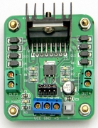
 Small DC motors can take significant current and they can’t be driven directly from the output pin of an Arduino or any other microcomputer chip . Details HERE: Therefore they need some sort of driver or current boost before you can control them. We use the motor driver board shown here. This has a chip that can control the current that the motors will need. Details are HERE:
You MUST use the battery power to run the robot motors in the following tests.
Speed and Direction Control:
The Motor Driver is connected to the RoboRED with 6 wires that can set the connection of each motor wire (to + or - of the battery) and also switch power to the motors on and off very quickly. Details [/DC-Motors#PWM HERE:] The direction and speed of each motor can be controlled independently.
TEST MOTOR DRIVER AND MOTORS:
Battery Case Setup:

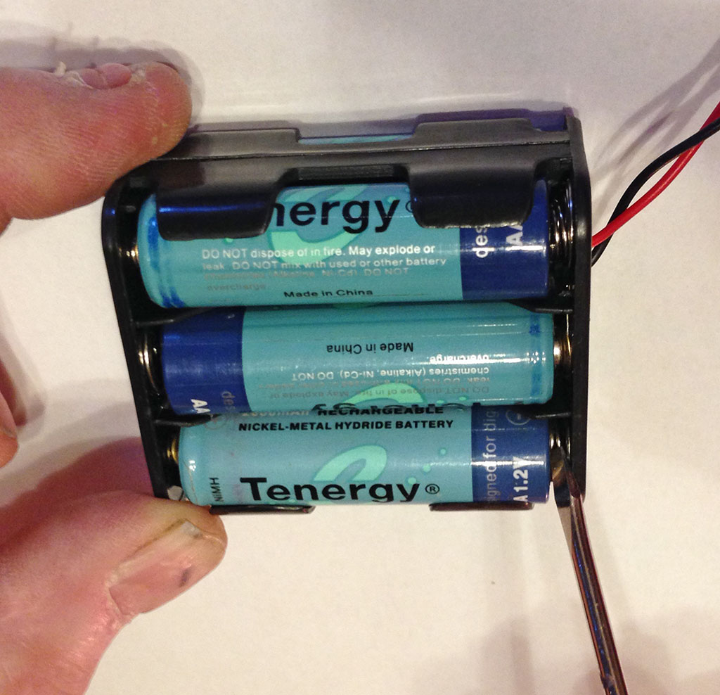
Insert 6 AA batteries into the battery case. Be careful about the orientation of each battery. Make sure each battery's + end is pushed towards the + contact. (The - end goes towards the coiled connection). You will want to use the small flat screwdriver (see Photo) to push the individual AA cells toward the + connection to make sure. (There is a lot of friction in a new battery case and they might not make contact). You should also rotate each AA cell a bit with you thumb to assure good contact. If the cells are new, it's also a good idea to run both ends against your blue jeans (or other slightly abrasive cloth) to clean the contacts.
We recommend rechargeable NiMH type batteries. You will also find the small flat screwdriver good to help get batteries OUT of the battery case. They are very tight and secure, but difficult to get in and out.
NOTE: If you want to use the optional power switch, instructions are at the bottom of this page.
Start with the battery case UNplugged from the Robo1. Find something to sit your robot on so that it's two big wheels are off the ground and it can't try to escape.
Download the motor driver library HERE and add it to your "libraries" folder.
How-To Install Libraries HERE:
Close and restart the Arduino IDE so that the library is recognized.
Cut and paste the test Software Sketch below into a new blank sketch window. Click Verify to make sure the software and libraries are installed correctly. Save it with some name like "MotorTest". Then click Upload to send it to the RoboRED.
NOTE! There is a small white button switch next to the blue power terminal board. SIGH! Some need to be UP and some need to be DOWN to power the motor driver. After you plug in the battery cable, look for a red led on the motor driver. Push the switch to the position where an led lights up. NOTE: You can also use the switch to turn the motors off temporarily to upload a new sketch.
Now UNplug the USB cable and plug in the Battery Case cable. (If you have wired in the switch, turn it on.) After several seconds you should see the LEDs on the motor driver board change brightness and one wheel should turn forward, stop and then turn in reverse, followed by the second motor. After a delay the test should run again. If the LEDs on the motor driver do NOT light up, the AA cells are not making good contact in the battery case (see above) or the button switch is in the wrong position.
.
Note: With the caster wheel towards you, check the motors operation: If you have the motors connected properly you should first see the LEFT-hand motor go forward and then reverse, followed by the RIGHT-hand motor going forward and then reverse. If a motor is rotating in the wrong direction, check the wiring as shown in the photos, and if necessary reverse the red and black wires where they are connected to the motor driver terminal block. (Thanks to Ganesh Shenoy for fixing this!)
/* YourDuino.com Example Software Sketch
  MotorDriverDEV
  YD_MotorDriver1 Library Test
  terry@yourduino.com
    V2.01 12/10/2016 Add Print statements
*/

/*-----( Import needed libraries )-----*/
#include <YD_MotorDriver1.h>

/*-----( Declare Constants )-----*/
// NOTE: Pins 9 (Motor1) and 10 (Motor2) are predefined, unchangeable
#define  Motor1A  8
#define  Motor1B  7
#define  Motor2C  6
#define  Motor2D  5

#define  RampDelay  250
/*-----( Declare objects )-----*/
YD_MotorDriver1 RobotDriver(Motor1A, Motor1B, Motor2C, Motor2D);
//YD_MotorDriver1 RobotDriver();

/*-----( Declare Variables )-----*/


void setup()   /*----( SETUP: RUNS ONCE )----*/
{
  Serial.begin(115200);
  Serial.println("YourDuino MotorDriver1 Ramp Up / Down Test");
  RobotDriver.init();

}/*--(end setup )---*/


void loop()   /*----( LOOP: RUNS CONSTANTLY )----*/
{
  Serial.println();
  Serial.println("Yourduino.com Robot Kit V2 Motors Test");
  delay(2000); // Give time to put the robot down!
  Serial.println("LEFT Motor Forward:  Motor 1 0..+400");
  for (int i = 0; i <= 400; i = i + 10)
  {
    RobotDriver.Motor1Speed(i);
    Serial.print(i, DEC);
    Serial.print(" ");
    delay(RampDelay);
  }
  Serial.println();
  delay(2000);


  Serial.println(" LEFT MOTOR Slow - Stop - Reverse: Motor 1 +400..0..-400");
  for (int i = 400; i >= -400; i = i - 10)
  {
    RobotDriver.Motor1Speed(i);
    Serial.print(i, DEC);
    Serial.print(" ");
    delay(RampDelay);
  }
  Serial.println();
  delay(2000);

  Serial.println("LEFT Motor slow to stop: Motor 1 -400..0");
  for (int i = -400; i <= 0; i = i + 10)
  {
    RobotDriver.Motor1Speed(i);
    Serial.print(i, DEC);
    Serial.print(" ");
    delay(RampDelay);
  }
  Serial.println();
  delay(2000);


  /*----( Ramp Motor2 Up and Down both directions )-------*/
  Serial.println("RIGHT Motor Forward: Motor 2 0+");
  for (int i = 0; i <= 400; i = i + 10)
  {
    RobotDriver.Motor2Speed(i);
    Serial.print(i, DEC);
    Serial.print(" ");
    delay(RampDelay);
  }
  Serial.println();
  delay(2000);

  Serial.println(" RIGHT MOTOR Slow - Stop - Reverse: Motor 2 +-");
  for (int i = 400; i >= -400; i = i - 10)
  {
    RobotDriver.Motor2Speed(i);
    Serial.print(i, DEC);
    Serial.print(" ");
    delay(RampDelay);
  }
  Serial.println();
  delay(2000);

  Serial.println("RIGHT Motor slow to stop:Motor 2 -0");
  for (int i = -400; i <= 0; i = i + 10)
  {
    RobotDriver.Motor2Speed(i);
    Serial.print(i, DEC);
    Serial.print(" ");
    delay(RampDelay);
  }
  Serial.println();
  delay(2000);

  //  delay(5000);
}/* --(end main loop )-- */

/*-----( Declare User-written Functions )-----*/


/* ( THE END ) */
You can also run the test with the USB connected. You might have to unplug and replug it to be recognized in the Arduino IDE. Click on the upper-right "Serial Monitor" icon.![]() Set the speed (lower right) to 115200
Set the speed (lower right) to 115200  to see the output.
If the above test ran OK, continue here. And if you haven't already this is a good time to put the wheels on!
TEST AND ADJUST MOTOR SPEEDS:
This test sketch will run the robot in slow, medium and fast speeds. You should place it on a smooth floor if possible. Carpet, especially thick carpet will slow or stop this robot. If you must run it on some carpet, you may have to change the MoveSpeed values to be higher, like SlowMoveSpeed 300, MediumMoveSpeed 360, FastMovespeed 390. But it will only run really well on a smooth floor.
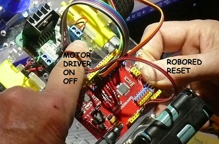
You can adjust the right VS left motor speeds to try to get the robot to move straight ahead. You can hold the robot in both hands, holding the RESET button on the right side of the RoboRED pressed until you put the robot down. Also make sure the caster wheel is pointing straight when you start. You can hold the RESET button with your right thumb, and click the Motor Driver White Button with your left finger, like in the following photo:
NOTE: To upload changes, you can leave the battery connected, turn the motors temporarily OFF with the button on the Motor Driver, plug in the USB and upload a new sketch. Then walk away, turn the motor driver on, hold your thumb on RESET and put the robot down for another run.
See this part of the test sketch:
#define SlowMoveSpeed 280
  #define SlowMoveAdjust 5 Adjust for straight move: - Left + Right??

 #define MediumMoveSpeed 300
  #define MediumMoveAdjust 5  Adjust for straight move: - Left + Right

  #define FastMoveSpeed 350
  #define FastMoveAdjust 5 // Adjust for straight move: - Left + Right
After you have found the best MoveAdjust values, write them down (or later cut and paste) for use in the other sketches.


/* YourDuino Basic Robot Kit V2 Motor Speed Test
 http://yourduino.com/sunshop2/index.php?l=product_detail&p=400
 - WHAT IT DOES:
 - Runs the robot motors at different speeds. Helps adjust Right-Left offsets
 - SEE the comments after "//" on each line below
 - CONNECTIONS:
 Pins 9 (Motor1 PWM) and 10 (Motor2 PWM) are predefined, unchangeable

// Label--Arduino Pin-- Motor Driver Pin
 Motor1A    pin 8           // INA
 Motor1B    pin 7           // INB
 Motor2C    pin 6           // INC
 Motor2D    pin 5           // IND

 - V2.10 11/10/2014
 Questions: terry@yourduino.com */

/*-----( Import needed libraries )-----*/
#include <YD_MotorDriver1.h>  // For control of the two DC Motors

/*-----( Declare Constants and Pin Numbers )-----*/

// NOTE: Pins 9 (Motor1) and 10 (Motor2) are predefined, unchangeable
#define  Motor1A  8
#define  Motor1B  7
#define  Motor2C  6
#define  Motor2D  5

#define  StartMoveSpeed    200  // Motor Driver value for start of motion

#define  SlowMoveSpeed     280
#define  SlowMoveAdjust     5   // Adjust for straight move: - Left + Right??

#define  MediumMoveSpeed   300
#define  MediumMoveAdjust   5  // Adjust for straight move: - Left + Right

#define  FastMoveSpeed     350
#define  FastMoveAdjust     5  // Adjust for straight move: - Left + Right

/*-----( Declare objects )-----*/
YD_MotorDriver1 RobotDriver(Motor1A,Motor1B,Motor2C,Motor2D); // Set pins


void setup()   /******************* SETUP: RUNS ONCE *****************/
{
  Serial.begin(115200);
  delay(1000);
  Serial.println("YourDuino Robot Kit V2 Motor Speed Test");
  //--NOTE:  Motor Pins set to OUTPUT by their libraries
  RobotDriver.init();
}//--(end setup )---

/************** LOOP: RUNS CONSTANTLY **************************/
void loop()
{
  Serial.println("Forward Slow Speed");
  ForwardSlow();
  delay(5000);
  Stop();
  Serial.println("---STOP---");
  delay(5000);

  Serial.println("Forward Medium Speed");
  ForwardMedium();
  delay(5000);
  Stop();
  Serial.println("---STOP---");
  delay(5000);

  Serial.println("Forward Fast Speed");
  ForwardFast();
  delay(5000);
  Stop();
  Serial.println("---STOP---");
  delay(10000);
  Serial.println("---END---");


}//--(end main loop )---


/*----------------( Declare User-written Functions )---------------*/

//------( MOTOR CONTROL FUNCTIONS )----------------
void ForwardSlow()
{
  RobotDriver.Motor1Speed(SlowMoveSpeed + SlowMoveAdjust);
  RobotDriver.Motor2Speed(SlowMoveSpeed - SlowMoveAdjust);
}
/*---------------------------*/

void ForwardMedium()
{
  RobotDriver.Motor1Speed(MediumMoveSpeed + MediumMoveAdjust);
  RobotDriver.Motor2Speed(MediumMoveSpeed - MediumMoveAdjust);
}
/*---------------------------*/
void ForwardFast()
{
  RobotDriver.Motor1Speed(FastMoveSpeed + FastMoveAdjust);
  RobotDriver.Motor2Speed(FastMoveSpeed - FastMoveAdjust);
}
/*---------------------------*/
void BackwardSlow(int HowMuch)
{
  RobotDriver.Motor1Speed(- SlowMoveSpeed );
  RobotDriver.Motor2Speed(- SlowMoveSpeed );
  delay(HowMuch);
  Stop();
}
/*---------------------------*/
void BackwardMedium(int HowMuch)
{
  RobotDriver.Motor1Speed(- MediumMoveSpeed);
  RobotDriver.Motor2Speed(- MediumMoveSpeed);
  delay(HowMuch);
  Stop();
}
/*---------------------------*/
void BackwardFast(int HowMuch)
{
  RobotDriver.Motor1Speed(- FastMoveSpeed);
  RobotDriver.Motor2Speed(- FastMoveSpeed);
  delay(HowMuch);
  Stop();
}
/*---------------------------*/
void Stop()
{
  RobotDriver.Motor1Speed(0);
  RobotDriver.Motor2Speed(0);
}
/*---------------------------*/
void SpinLeft(int HowMuch)
{
  RobotDriver.Motor1Speed(MediumMoveSpeed);
  RobotDriver.Motor2Speed(- MediumMoveSpeed);
  delay(HowMuch);
  Stop();
}
/*---------------------------*/
void SpinRight(int HowMuch)
{
  RobotDriver.Motor1Speed(MediumMoveSpeed);
  RobotDriver.Motor2Speed(- MediumMoveSpeed);
  delay(HowMuch);
  Stop();
}
/*---------------------------*/


//*********( THE END )***********
TEST ROBOT MOVES AND CREATE YOUR OWN ROBOT CONTROL PROGRAMS
Next is the section that shows details of making your own Robot Control Programs.
Go To the Next Section: Robot Commands and Editing OR back to the Main Menu
OPTIONAL: Connect a Power Switch
The Basic Robot does not require any soldering or special wiring. Many people plug the battery case cable in or out to control power to the robot. If you would like to use the optional switch included in the kit, here are instructions:
- Physically install the switch (tight fit!) ; you might have to file the hole a little.
- Find some small wire; cut two pieces about 5 inches long, strip the ends about 1/2 inch.
- Connect the wire ends to the switch. The rear two contacts will be active when the switch is flipped forward.
- Solder the wires to the switch, OR
- Put the wire end through the hole in the contact, wrap tightly around it and tape securely.
- Cut the + (Red) wire of the battery case approximately in the center; strip the ends about 1/2 inch.
- Connect the wires from the switch to the battery case wire (either one is OK).
- Plug the battery case connector into the RoboRED and check that the switch works.
Please email comments, critiques, suggestions and questions to: terry@yourduino.com