SD-Card-Logger
Jump to navigation
Jump to search
SD Card Example Logging Temperatures
This example uses an Arduino RoboRed with a few DS18B20 temperature sensors, a SD card Module, and a 4 line LCD screen to log temperatures as a .CVS file. A .CVS file is a format that allows for data to be very easily read by any spreadsheet program (such as Excel or Google Sheets). By logging data onto an SD card as a .CVS, the SD card can simply be put into a computer and the data recorded can be easily worked on, and graphs can be created.
Hardware:
Temperature Sensors
Overview:
The DS18B20 temperature sensor is an electronic thermometer with a high accuracy. They also use a 1 wire bus to communicate, which means we can have lots of sensors while only using one pin. To communicate with these sensors we will use the Dallas Temperature Control Library, found HERE.
Wiring:
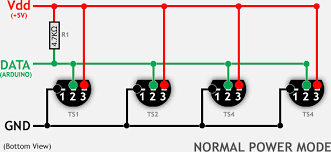
The sensors should all be attached with their data pins attached to pin 9. Gnd to Gnd, and Vdd to 5 V. If you are using the small chip sensor orient them as shown below. If you are using the waterproof version then red is 5V, black is Gnd, and white is data. Note that a roughly 4.7 K resistor should be put between the data line and Vdd. This diagram shows an easy way to wire the sensors. It's possible to put all the temperature sensors on one wire because each one has a unique address.
LCD Screen
LCD screens allow the user to know what is going on with the Arduino without needing to connect to a computer. LCD displays are available on YourDuino.com. These displays will use the great Library written by F Malpartida . You should download that LibraryHERE (Click) (Get the latest file such as NewliquidCrystal_1.3.4.zip ) If you try to Verify and you see this: "error: 'LiquidCrystal_I2C' does not name a type" ...this means you do not have the library installed correctly. See: How-To-Install-Libraries
  NOTE!! Move any other LCD libraries to another folder,or rename or delete them.

  The LCD Screen communicates with the Arduino using a method called I2C. The small circuit board on the back interfaces a 2-wire I2C "I Squared C" bus (plus Ground and +5V power) to the many pins on the LCD display itself. This allows running the display from only 2 signal pins on Arduino. The YourDuino RoboRED (UNO Compatible) has a 4-pin connector that works well for this type display. If you are using the RoboRed then connecting the LCD screen is very easy. The 4 pins in a row next to the analog pins on the Arduino are labeled GND, VCC, SDA, SCL. Each of these will correspond to a pin on the LCD backpack, simply hook them up one to one. If you are not using the RoboRed then wire as follows:

  LCD-Arduino
  GND - GND
  VCC - 5V
  SDA - A4
  SCL - A5

  For the I2C communication method each object connected to it must have an address. For LCD screens from YourDuino.com the address will either be

(0x27, 2, 1, 0, 4, 5, 6, 7, 3, POSITIVE)
or
(0x3F, 2, 1, 0, 4, 5, 6, 7, 3, POSITIVE)
Try the first, and if it doesn't work then try the second. In addition, or if you are using another type of LCD screen, there is an sketch which will allow you to directly view the addresses of all connected devices, it can be found [/LCD-Blue-I2C#scan HERE].
SD Card Module
Overview
The SD Card Module allows for reading and writing data on an SD card. This will be used to record our temperatures for future use. Like most modules we will use a library, sdFAT, to make things easier. sdFat is available HERE.  SD Cards work only at 3.3V  and both the power and I/O levels must be accommodated. The module used here uses FETs for level shifting and a 3.3V regulator for power when operating from 5.0V . A switch allows the module to be used at 5V or 3.3V. This module also has a MicroSD socket on the back side, and we have tested 2Gb and 4Gb MicroSD cards plugged in there. They worked OK with the SdFAT library. These cards are formatted FAT32 and SD/HC. SD Cards need to be reformated to work well with the SD Card Module. The Panasonic's formatter, available here: works best. The SdFAT Library also includes a sketch that can format cards well. SD Card Modules are available from YourDuino HERE.

  NOTE:  There are many variables in getting SD cards to work well with Arduino. Some SD cards work fine, some do not.
  You may have to try a few. Most cards have good SPI read performance but cards vary widely in SPI write performance. Write performance is limited by how efficiently the card manages internal erase/remapping operations. The Arduino cannot optimize writes to reduce erase operations because of its limited RAM.


  SanDisk cards generally have good write performance. They seem to have more internal RAM buffering than other cards and therefore can limit the number of flash erase operations that the Arduino forces due to its limited RAM.

  Some Dane-Elec cards have a write speed that is only 20% as fast as a good SanDisk card.
Wiring
The SD card module is wired as follows:

  (Arduino Pin) - Module Pin

  10 (SS) - CS

  11 (MOSI) - DI

  12 (MISO) -DO

  13 (SCK) -CLK


  and G to GND and + to 5V

  Switch the switch to 5V
Software Overview:
Setup:
On start up it activates the libraries, and picks a file name to log the data under. Then it writes the file headers, this will be the labels for each column of our spreadsheet. It also brings the name of the file being created up on the LCD screen.
Loop:
Loop counts up whatever the delay between readings is and then takes a reading.
Functions:
Log Data:
  This function is called by loop and is what performs the data logging action. It first reads in all the temperature sensors and writes that data to the LCD screen. Then it writes the same data to the SD card.
  Write Header:
  This function creates the header mentioned earlier, which is the first line of our .CSV.
A couple of notes:
There is a line in the declare constants section of the code that is as follows:
  bool DEBUG = 0; //set to 1 for serial monitor debug, set to 0 to turn off serial coms.
  what this does is turn on and off all the places that the sketch reports data over the serial monitor. When you are getting things up and running set this to 1 and open your serial monitor for lots of helpful debugging data. If you are going to use the sketch with the Arduino not connected to a computer set this to 0 as there can sometimes be issues when the Arduino tries to talk over serial but there is no computer attached.
The Sketch:
/*YourDuino SD Card Temperature Logger
  V1.3 02/08/2018

  This sketch will log multiupl Temperature sensors and record the data as a .CSV file onto an SD card.
  This allows easy transfer of data to a computer where it can be opened in Excel or similar programs
  and worked on.

  Uses SD Card Module availabe here:http://www.yourduino.com/sunshop/index.php?l=product_detail&p=246
  Uses DS18B20 Temperature sensor here:http://www.yourduino.com/sunshop/index.php?l=product_detail&p=134
  Waterproof Version here: http://www.yourduino.com/sunshop/index.php?l=product_detail&p=151

  Wiring: SD Card Module
  (Arduino Pin) - Module Pin
  10 (SS) to CS
  11 (MOSI) to DI
  12 (MISO) to DO
  13 (SCK) to CLK
  and G to GND and + to 5V
  Switch the switch to 5V

  Wiring: Temperature Sensor
  CONNECTIONS: (Holding chip with pins down, label towards you)
  - Left  pin:  Ground
  - Right pin:  +5V
  - Center pin: Arduino Pin 9 and ALSO "Pullup Resistor":
  - Center pin: to 4700 (4.7K) or 5K resistor * (other end goes to +5V)
    NOTE: Two 10K resistors connected in parallel can be used.

  Wiring: Status LED
  Connect and LED to pin 8 (don't forget 220 reisitor between pin and LED)

  Based on YourDuino Temperature Sensor Example and SDFat dataLogger example.
*/

/*-----( Import needed libraries )-----*/
#include <SPI.h>
#include "SdFat.h"
//#include <OneWire.h> note that the new Dallas Temperature library does not require oneWire (it actually includes it inside the library).
#include <DallasTemperature.h>
#include <LiquidCrystal_I2C.h>
#include <Wire.h>  // Comes with Arduino IDE

/*-----( Declare Constants )-----*/
#define ONE_WIRE_BUS 9
#define STATUS_LED 8
// Log file base name.  Must be six characters or less.
#define FILE_BASE_NAME "Data"


/*-----( Declare objects )-----*/
/* Set up a oneWire instance to communicate with any OneWire device*/
OneWire ourWire(ONE_WIRE_BUS);

/* Tell Dallas Temperature Library to use oneWire Library */
DallasTemperature sensors(&ourWire);

// set the LCD address to 0x3F for a 20 chars 4 line display
//                    addr, en,rw,rs,d4,d5,d6,d7,bl,blpol
LiquidCrystal_I2C lcd(0x3F, 2, 1, 0, 4, 5, 6, 7, 3, POSITIVE);  // Set the LCD I2C address

/*-----( Declare Variables )-----*/
// SD chip select pin.  Be sure to disable any other SPI devices such as Enet.
const uint8_t chipSelect = SS;

// Time in Seconds for next data record.
uint32_t logTime;

// Interval between data records in seconds.
// The interval must be greater than the maximum SD write latency plus the
// time to acquire and write data to the SD to avoid overrun errors.
// Run the bench example to check the quality of your SD card.
const uint32_t SAMPLE_INTERVAL = 600;

//Number of attached temperature sensors
const uint8_t SENSOR_COUNT = 3;

bool DEBUG = 0; //set to 1 for serial monitor debug, set to 0 to turn off serial coms.

/*-----( SD Stuff )-----*/
// File system object.
SdFat sd;

// Log file.
SdFile file;

// Error messages stored in flash.
#define error(msg) sd.errorHalt(F(msg))

void setup() /*----( SETUP: RUNS ONCE )----*/
{
  const uint8_t BASE_NAME_SIZE = sizeof(FILE_BASE_NAME) - 1;
  char fileName[13] = FILE_BASE_NAME "00.csv";

  pinMode(STATUS_LED, OUTPUT); //Set the Status LED pin to output
  digitalWrite(STATUS_LED, HIGH); //Turn On the status LED
  if (DEBUG == 1) //debug mode switch
  {
    Serial.begin(9600);//Start Serial communication
  }
  lcd.begin(20, 4);        // initialize the lcd for 20 chars 4 lines, turn on backlight

  // ------- Quick 3 blinks of backlight  -------------
  for (int i = 0; i < 3; i++)
  {
    lcd.backlight();
    delay(250);
    lcd.noBacklight();
    delay(250);
  }
  lcd.backlight(); // finish with backlight on

  //-------- Write characters on the display ------------------
  // NOTE: Cursor Position: Lines and Characters start at 0
  lcd.setCursor(0, 0); //Start at character 4 on line 0
  lcd.print("YourDuino SD Logger");
  if (DEBUG == 1) //debug mode switch
  {
    // Wait for USB Serial
    while (!Serial)
    {
      SysCall::yield();
    }
  }
  delay(1000);
  //Start Dalas Temperature Library
  sensors.begin();

  // Initialize at the highest speed supported by the board that is
  // not over 50 MHz. Try a lower speed if SPI errors occur.
  //For this sketch 4 MHz works just fine, but higher speeds may be posible depending on SD card/Hardware
  if (!sd.begin(chipSelect, SD_SCK_MHZ(4)))
  {
    sd.initErrorHalt();
  }

  // Find an unused file name.
  if (BASE_NAME_SIZE > 6)
  {
    error("FILE_BASE_NAME too long");
  }
  while (sd.exists(fileName))
  {
    if (fileName[BASE_NAME_SIZE + 1] != '9')
    {
      fileName[BASE_NAME_SIZE + 1]++;
    }
    else if (fileName[BASE_NAME_SIZE] != '9')
    {
      fileName[BASE_NAME_SIZE + 1] = '0';
      fileName[BASE_NAME_SIZE]++;
    }
    else
    {
      error("Can't create file name");
    }
  }
  if (!file.open(fileName, O_CREAT | O_WRITE | O_EXCL))
  {
    error("file.open");
  }
  if (DEBUG == 1) //debug mode switch
  {
    // Read any Serial data.
    do
    {
      delay(10);
    }
    while (Serial.available() && Serial.read() >= 0);

    Serial.print(F("Logging to: "));
    Serial.println(fileName);
    Serial.println(F("Type any character to stop"));
  }
  lcd.setCursor(3, 1); //Start at character 4 on line 1
  lcd.print("Loggin to:");
  lcd.setCursor(0, 2);
  lcd.print(fileName);

  // Write data header.
  writeHeader();

  logTime = 0;
  delay(2000);
  digitalWrite(STATUS_LED, LOW); //turn off Status LED
}/*--(end setup )---*/

void loop() /*----( LOOP: RUNS CONSTANTLY )----*/
{
  logData(); //Call the Log Data Function
  delay(SAMPLE_INTERVAL * 1000); //wait for log time (in mils)
  logTime = logTime + SAMPLE_INTERVAL; //Set the new logtime

  // Force data to SD and update the directory entry to avoid data loss.
  if (!file.sync() || file.getWriteError())
  {
    error("write error");
  }
  if (DEBUG == 1) //debug mode switch
  {
    if (Serial.available()) //Stop Recording data if Serial Monitor detects a character.
    {
      // Close file and stop.
      file.close();
      Serial.println(F("Done"));
      SysCall::halt();
    }
  }
} /* --(end main loop )-- */


/*-----( Functions)-----*/
// Write data header creates the first line of the CSV with the titles of each column
void writeHeader()
{
  file.print(F("Seconds"));
  for (uint8_t i = 0; i < SENSOR_COUNT; i++) {
    file.write(',');
    file.print(F("Temp Sensor:"));
    file.print(i, DEC);
    file.print(F("( F)"));
  }
  file.println();
}


// Log a data record.
void logData()
{
  if (DEBUG == 1) //debug mode switch
  {
    Serial.println("New Log");
  }
  digitalWrite(STATUS_LED, HIGH); //Turn on Staus LED

  lcd.clear();// clear the LCD screen
  lcd.print("Time Elapsed:");
  lcd.print(logTime);
  lcd.print("  ");

  lcd.setCursor(0, 1); //set the cursor to the second line
  //create a one demensional matrix to hold the data from all the sensors
  uint16_t data[SENSOR_COUNT];

  // Read all sensors to avoid SD write latency between readings.
  sensors.requestTemperatures(); // Send the command to get temperatures
  for (uint8_t i = 0; i < SENSOR_COUNT; i++) //For each sensor put the data into the matrix
  {
    data[i] = sensors.getTempFByIndex(i); //log temperature
    if (DEBUG == 1) //debug mode switch
    {
      Serial.print("Temperature Sensor"); //write the data to the Serial Monitor
      Serial.print(i);
      Serial.print(" F:");
      Serial.println(data[i]);
    }
    lcd.print("S"); //print the data on the LCD screen
    lcd.print(i);
    lcd.print(":");
    lcd.print(data[i]);
    lcd.print("  ");
  }
  // Write data to file.  Start with log time in seconds.
  file.print(logTime);

  // Write data to CSV record.
  for (uint8_t i = 0; i < SENSOR_COUNT; i++)
  {
    file.write(',');
    file.print(data[i]);
  }
  file.println();
  digitalWrite(STATUS_LED, LOW);
}
//==============================================================================


/* ( THE END ) */