SHED-Article1
ARDUINO: Tools and Materials
CONTACTS:
Terry King terry@yourduino.comterry@terryking.us USA: 1-802-439-5503
  Jude Woodside sales@theshedmag.co.nz Tel: 09 302 3172 Mob: 027 444 9906
  Terry Snow editor@theshedmag.co.nz Ph (09) 302 3172
NOTES:
- [square brackets denote undecided words or items]
- LAYOUT: I expect you'll decide all of that; this is just intended to show the relationship of the graphical elements I used here.
- GRAPHIC ELEMENTS: I will provide separate original .jpgs for images shown here; these are downsized.
- SIGH... I am known for inconsistent use of Bold, Italic etc. Need to fix this.... Guidance ??
--------( Beginning of editorial material )---------
[TITLE ???]
INTRO:
This is all about Tools and Materials. Woodworkers often start out learning a few tools, looking at different woods, and building a first project, often from a plan. Here we will show you the types of Materials and parts available, and the Tools you can use to build interesting and useful devices.
Arduino is a low cost [NZ$ nn] microcomputer that is the centerpiece of the new toolset of the 2000's. It brings us a large set of capabilities to make things that are active, decision-making, and tireless.
The main Arduino Toolset is free, open-source software that works on almost any computer. The Arduino microcomputer board designs are open-source and can be freely copied and upgraded. One upgrade is the YourDuinoRobo1 shown here [below] that is available in the "Shed Starter Set" [??TITLE??].
Arduino allows you to make things that are aware of conditions (like temperature, light, etc.) in the real world around it. You decide what decisions it should make and what actions it should take. Actions can include control of lights, motors, valves, heating/cooling, communications and much more. You wire together ideas and electrical things... with today's equivalent of Number 8 Wire.
WHAT CAN YOU DO WITH ARDUINO? / WHAT ARE PEOPLE DOING WITH ARDUINO??
[under Construction: need photos and permissions]
- Aquaponic systems that control the environment that grows fish and vegetables in a symbiotic relationship.
- Automatic control of incubation of Sea Turtle eggs in Mexico
- Stored product programs to create bent-metal parts on a hydraulic system in Croatia
- Control of an elevator and multiple conveyor sections in a food warehouse in Puerto Rico
- Miniature GPS guided and gyro controlled aerial drones with cameras.
- And lots of much simpler things, like controlling my shop lights and fans.
GETTING STARTED.. WHAT YOU NEED:
- Arduino-compatible Microcomputer board
- Desktop or Laptop Computer (Only for programming Arduino)
- Interesting input and output devices to hook up and learn about.
The [Shed Starter Set] is an easy low-cost way to get started.
[GRAPHIC: Reader, Personal Computer, USB Cable, YourDuino board, Input and Output devices].
Most Wood and Metal-working is physical and right there in your face. But Electricity and Software are Invisible! Don't worry about it; we'll show you how to make them visible and work with them.
INSTALLING THE FREE ARDUINO SOFTWARE:
The Arduino software you'll use looks virtually the same on Windows, MAC or Linux, but the Installation procedures are different. Below, you can pick which one you need. The Arduino IDE (Integrated Development Environment) (WikiPedia) is the one place you do almost everything about Arduinos and Arduino software Development. [NOTE about Versions needed]
After Installation, or if your board is already installed, continue here:
{| class="captionBox" style="float: right" | class="captionedImage" | 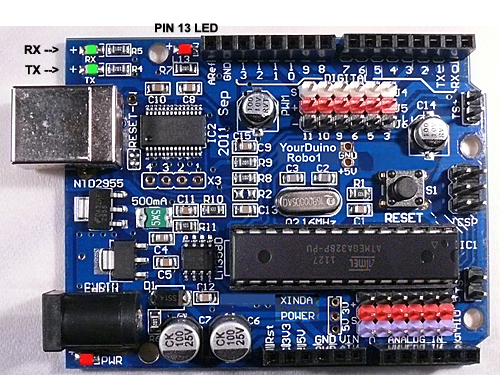 |- | class="imageCaption" | LCSS-yourduino-robo1-500.jpg |}CHECK OUT THE YourDuinoRobo1:

At the lower left is the PWR LED which should light up whenever the board is plugged into a USB connection, or has power from an external power supply.
  At the upper left there are two green LEDs which will blink when a software sketch is being downloaded to the board, or other data is being transferred over USB.
  At the top is a red LED which is internally connected to pin 13 through a current-limiting resistor. It should blink after you load the example BLINK software sketch.
OK, so you've got your YourDuino plugged in and running. The POWER "ON" LED is on, right? And the "13" LED is blinking? (This may be a little different for the various Arduino copies, and the '13' LED may or may not blink now).
IT'S SOFTWARE TIME:
Let's take a little while to get used to writing Arduino Software, then we'll come back and start connecting your Starter Set parts and making more interesting things. On your desktop you should now have the Arduino ICON like this:
|
|
| LCSS-IDE1.jpg |

|
|

Click on it, if you haven't already, and you should see the "Arduino IDE Window" pop up like this:
You'll use the IDE to make Software VISIBLE! Here you will develop your own software to make Arduino into what you want it to be.
SKETCHES:
The visible text of an Arduino software program is called a SKETCH. But the Sketch becomes alive when you upload it to your Arduino. Let's walk through looking at a Sketch and Verifying it and Uploading it:
|
|
| LCSS-IDE-Blink.jpg |

Click on FILE and then move your mouse (slowly.. It's Fussy!) over EXAMPLES and BASICS and BLINK so it looks like this (right):
|
|
| LCSS-IDE-BlinkCode.jpg |

And CLICK. There are lots of examples that come with the free Arduino software system, and we will look at some of them later, as well as make our own.
A new IDE window should pop up and look like this (BLINK): Wow.. A bunch of new stuff.
Let's slow down and "Watch Closely Now"! Don't worry about the unfamiliar words yet!
Notice that a lot of the text is [GREY]. All of that is just "Comments" for you to read to help understand the Sketch. When you write software, you should also use "Comments" to explain to others what you are doing. (Arduino itself totally ignores these comments).
Now, let's go through changing software, Verifying it, and Uploading it to see Arduino DO it. We'll use the BLINK example for now, but in a while you'll write your own programs.
Every Arduino Program has the same basic structure:
- SETUP - Runs Once at the beginning
- LOOP - Runs over and over again, forever
You will read a LOT of program "Code" that other people wrote, in the future. You HAVE to "Watch Closely Now" and really see the details. Read the example through carefully, a couple of times. Note the colored special words that are Instructions. These are unique words that tell Arduino what to do. They have to be spelled perfectly!
What SETUP does: Instructs Arduino about things that need to be done once. Arduino Digital Pins can be used as either INPUT or OUTPUT. You have to tell Arduino when a Pin will be used as an OUTPUT. In this example, there is one line that tells Arduino that Pin 13 must be an OUTPUT.
| external image Arduino-IDA-Pinmode1.jpg |
Note the COLOR of the lettering. The Arduino IDE changes the color of words as it recognizes them as special instructions. Let's mess with them:
pinMode: Note that when Instructions are two words run together, like pinMode, the beginning of the SECOND word is Capitalized. So.. Change the Capital "M" to "m". Note the color changes to black. Hmmm. Click the VERIFY
|
|
| external image ArduinoIDE-VerifyButton.jpg |
button.

  You will get an ERROR message:
|
|
| external image ArduinoIDE-pinmode-error.jpg |
Fussy, Fussy, Fussy! Yep, every letter has to be correct and also correct upper or lower case.
Change it back. Check the color. Click Verify again. OK??
What does VERIFY do?? {| class="captionBox" | class="captionedImage" |  |- | class="imageCaption" | external image ArduinoIDE-VerifyButton.jpg |}
A LOT! More details later, but Verify is a program in your main computer that goes through every Instruction in your Sketch (Ignoring "Comments") and checks it against the list of valid Instructions, and checks that the structure and sequence of the statements in the Sketch are correct. Fussy, Fussy! If that's OK, then it "compiles" or "translates" the sketch into the actual machine code that Arduino really runs on. It saves that 'ready-to-run' code for you to Upload to Arduino and run. Other systems would call this process "Make" or "Compile".
What does UPLOAD do?? {| class="captionBox" | class="captionedImage" |  |- | class="imageCaption" | external image ArduinoIDE-Upload-Button.jpg |}
First, Upload runs Verify to check and compile your program. Then it communicates to your Arduino over the USB connection, resets the Arduino chip, and talks to software already on Arduino (called the BOOTLOADER(W)) to load your new program into the Arduino's memory (Arduino will remember it, even if the power is turned off). Then it restarts Arduino and your program runs it's SETUP section and then repeats the LOOP section. Your Sketch is running!
Start Making Changes:
Ok, let's look closely and then make a few changes to the sample BLINK program:
|
|
| external image Code-Blink1.jpg |

The LOOP section of your program does all the instructions in the section, and then "loops" back to the top and starts it again, over and over.
NOTE the "Curly Brackets" { and } Notice that the beginning and end of the section is "inside brackets". You will see many sections of bigger programs that are grouped by these "brackets".
Now, let's look in detail at the instructions:
Instruction: digitalWrite
This instruction sets an OUTPUT PIN to either HIGH (connects it to +5 V) or LOW (Connects it to GND). Remember: HIGH = 1 = ON = 5V . So, the first line in LOOP sets PIN 13 to HIGH. There is an LED and resistor already connected to PIN 13, so the LED lights up.
Instruction: delay
The delay instruction just waits for a period of time. The VALUE used with delay is in Milliseconds (1/1000 second). So delay(1000); waits for 1000/1000 seconds (1 second). We'll change that soon.

 NOTE: the ";" Notice that every instruction is followed by the character " ; " which is like a period that tells the end of the sentence.

 Change the delay so that the LED blinks differently:
  Time to mess about and try some things! Maybe we'll break it. Then we'll fix it..

  Suggestion: Save your own version of BLINK so you can always go back to the original one. Go to File and Save As and call it something like MyBlink. This will go in your SKETCHBOOK where you'll save your own programs. If things are messed up, just go back to to What Worked and start again... The sawdust goes right back into the wood!

  Now go change the VALUE in a delay statement to change the way the LED blinks. Think about the the 4 instructions in LOOP. What's happening??

 Turn the LED on. Wait and look at the LED.
 Turn the LED off. Wait and look at the dark.

  So, let's change the ON time to be short. Maybe 50 Milliseconds. That's 1/20 of a second. Then try 10 milliseconds. The LED is only on 1/100 of the time. Can you still see it blink? How about 1 millisecond?

  Each time you make a change, click Upload
|
|
| external image ArduinoIDE-Upload-Button.jpg |
which will first Verify and then Compile your program and send it to Arduino. Notice that each time you do this the LEDS that are marked "Tx" (Transmit) and "Rx" (receive) flash as your main computer communicates with your Arduino.

  Try some combinations of ON and OFF times. Like ON 1000 and OFF 50.

  Try making both ON and OFF times shorter and shorter. If you make the ON and OFF times short enough, your eye will no longer see blinking, because of "Persistence of Vision"(W) which happens when there are more than about 25 blinks per second. So, hmmm.... if you make the LED be ON for 1/50 of a second and OFF for 1/50 of a second that should do it. So try 1000/50 = 20 Milliseconds. Put 20 for both the ON and OFF times. What do you see?? How about 10 Milliseconds each? Depending on your personal eye's physiology, at some speed you will not see any more blinks.

  All right. You're the Programmer! You can save any of the sketches for use later on. Then go to File>Sketchbook and you'll see them.
CONNECTING and BREADBOARDING: We'll start hooking up Electronics Parts
The idea here is that wires and electronics parts like LEDs and RESISTORs can be plugged into the BREADBOARD and then easily be removed or changed. The holes in the BREADBOARD go down into little sockets with metal contacts. Sections of the BREADBOARD have rows or columns that are all connected together, making it easy to have multiple things connected together.

  Here's some detail of how the BREADBOARD that we use in this kit is organized:
| external image BreadBoard-1.jpg |
The Horizontal Rows have 5 holes (abcde) and (fghij) with sockets that are connected together. Any wires or parts that are plugged into this row are connected together.
The Vertical Columns (+Red and -Blue) have the same connection running all the way down. We will use these to connect 5V on our YourDuino board to the +Red and to connect GND on our YourDuino board to -Blue.
|
|
| Breadboard-8cm-2-500.jpg |

We will orient the breadboard as shown on the right, and mainly use the upper +Red row and the bottom -Blue row. Often we think of these parallel lines as "Rails" like railroad rails. The top red rail is the "+5 Volt Rail" and the bottom blue rail is the "Ground Rail". "Voltage Rails" (Wikipedia) is a common terminology in electronics.
What about wires? Locate the "40 pin flat cable" and the "Male-Male Pin Connectors" in your set. To start we will connect the "5V Rail" to "5V" on the YourDuino board.
WIRES:
We will use the "CableMaker 40 pin flat cable" in your kit for wires. It looks like this:
|
|
| FlatCable-Separate-Ends-800.jpg |

|
|
| 40-pin-MM3-300.jpg |

You can easily strip off one or more wires, or strip off a section to use as a cable. The ends of these wires are female connectors that can plug onto the connectors on the Robo1 or a "Sensor Shield". But what about the breadboard?? It needs a wire with a male end to plug into it. Here (right) is the answer. Your kit has 2 of these with 40 pins each. You can cut or snap off the number of pins you need. For now, snap/cut off about 6 single pins. Lots more about Cabling HERE:
|
|
| LCSS-LED-YD1-500.jpg |

Now, let's connect your Breadboard to the YourDuino board. Strip off some wires from the flat cable as needed.
Run a Red wire from a +5 pin on the YourDuino to the +Red Rail on the breadboard. Run a Blue wire from a GND pin on the YourDuino to the -Blue Rail on the breadboard. Now it's easy to connect things to the 5V (+Red) Rail or the GND (-Blue) Rail.
|
|
| LCSS-LED1-200.jpg |

See the close-up photo here, and plug a 220 Ohm (Red-Red-Brown) resistor and a red LED (Long pin to the left) into the Breadboard as shown. Now add a wire (Black is shown) from the same vertical strip as the LED to the GND Rail. Connect another wire (Green is shown) to the same vertical strip as the left end of the resistor, and use a pin to plug it into the YourDuino socket labelled 13. (Use male-male pins where you need a male end to plug into the breadboard or YourDuino)
Time to Power Up! Plug the USB cable from your computer into the YourDuino. Its PWR LED should come on. And the pin 13 LED should be blinking in the way you last programmed it. If necessary load the original GOBP (Good Old Blink Program!) and Upload it to YourDuino. Your setup should look like the photo on the right above. AND the LED you just wired up on your Breadboard should blink the same as the 13 LED on YourDuino. NO? Recheck that you have it wired like the photos, and the the LED's longer lead is to the left.
Let's figure out what's really happening here. Unplug the wire from YourDuino pin 13 (keep the pin with it). Now try two things:
- Plug the free end of the wire into the +5V Rail. It should light up.
- Plug the free end of the wire into the GND Rail. It should be off.
Try it a few times, like 1 second to +, 1 second to GND. Now plug it back into YourDuino Pin 13. I should blink again.
What's happening here?? The YourDuino is doing exactly the same thing automatically that you did manually! It is connecting the circuit connected to pin 13 to the +5V Rail and then connecting it to the GND Rail.
That's how "Digital Outputs work.
OK, you have a good beginning in setting up YourDuino, Programming it, and wiring up external devices. Now, let's slow down a bit. In our next section, we'll think about what's going on here, which is CIRCUITS.
And what's all this stuff about PINS , BITS , ONES and ZEROS , HIGH and LOW... ? ?
PINS... BITS... ONES and ZEROS... HIGH and LOW... ... YOU'LL KNOW!!
OK, Fans, it's ELECTRICITY Time ! And, the weird thing about electricity is it's INVISIBLE! We just need to learn how to make it visible to us. Here's how to think about it:
5V = HIGH, GND = LOW:

DIAGRAMS:
Often an actual circuit (like the YourDuino and Breadboard hookup) gets to be a confusing bunch of wires and components going in all directions. To keep our heads together, we draw Circuit Diagrams to show what we're trying to do. Notice the Symbols used in the diagram above for things like: SWITCH, RESISTOR, LED. And there are Labels on connections, like GND, INPUT, OUTPUT, ARDUINO etc.

  There's our theme music again: "Watch Closely Now"... In the diagram above, we have added a dose of reality: Arduino is powered (usually) by +5.0 Volts of DC (Direct Current).

  We show the +5.0 Volts connected HIGH on the top. Look closely at YourDuino.. find the PIN marked "5V". that's the one +5.0V power is connected to. Where does it come from?? (To start, from the USB cable from your computer to Arduino.)

  We show GND (Ground) connected LOW down on the bottom of YourDuino. Look at YourDuino (or a photo).. find the PIN marked "GND". ("Watch Closely Now" - There are actually 3 "GND" PINS).
RAILS !
The parallel lines of +5V HIGH on the diagram, and GND - LOW on the diagram are called "RAILS". Kind of like railroad RAILS across the top and bottom. Almost everything that happens on Arduino is between the +5V HIGH RAIL and the GND-LOW (0.0V) RAIL.
DIGITAL "SIGNALS":
When a PIN (or wire or connection) changes from 0 to 1, or 1 to 0, we say it is a SIGNAL. Kind of like someone raising up a flag or lowering it.
- OUTPUT SIGNALS: An LED or Buzzer connected to to an Arduino OUTPUT can "signal" you that something has happened.
- INPUT SIGNALS: If you push a button that changes an INPUT, you "signal" Arduino that something should be done.
BITS !
Oh, um.. what's a BIT anyway? It is a Binary InTeger which is a number which has only two possible values: 0 and 1. Each YourDuino Input or Output PIN is one BIT inside Yourduino. (A GROUP of 8 BITS is called a BYTE. Bet you knew that!).
DIAGRAMS:
OK, Look again at the diagram above:
The pushbutton switch causes the INPUT to change from LOW to HIGH, which is a "signal" to Yourduino.
Yourduino can change the OUTPUT from LOW to HIGH, causing electricity to flow through the LED, light it up and "signal" you.
OK, another one of those tekkie words: DIGITAL: This means Arduino will use these Pins only as ON or OFF.
You will hear "Digital" things described three or four ways: but "0" and "OFF" and "LOW" mean the same thing. And "1" and "ON" and "HIGH" mean the same thing.
"DIGITAL" values
0 |
1 |
OFF |
ON |
LOW |
HIGH |
0.0 Volts(GND) |
5.0 Volts(5V) |
Let's listen to the way these terms are used by people talking about this Microcomputer Stuff:
"When SOFTWARE inside the Arduino sets an OUTPUT PIN to a "1" it is "ON" and "HIGH" . Arduino connects the PIN to the HIGH RAIL which is 5.0V (5V).
When SOFTWARE inside the Arduino sets an OUTPUT PIN to a "0" it is "OFF" and "LOW". Arduino connects the PIN to the LOW RAIL which is 0.0V (GND)."
[??] Sorry for the multiple names for the same things, but those names are widely used, and it's time for you to know them...
PINS, BITS, ONES and ZEROS, HIGH and LOW... (Make Sense?? We hope so! )
[??] No?? Please email terry@yourduino.com and ask questions and make suggestions...
OK, time to stop talking and hook real things up to those INPUTS and OUTPUTS. Look at YourDuino again for a minute. You'll get to know it well:

Take a couple of minutes to look at it closely. If you haven't done much detailed electronics it looks like a jumble. But slow down and look at the different parts.
What's important to us first?? We need to connect stuff, so we'll look at the connectors. All regular Arduinos have the same overall size and the same long black connector strips across the top and bottom edges. These are female sockets that pins can plug into. YourDuino has added two sets of 3-pin connectors to make it easy for you to connect things. Let's look at the details. First, here is the top connector:

The Sockets (Places you can connect wires and devices to) are numbered 0 to 13 from right to left. These are the DIGITAL INPUT/OUTPUT connections. You can push wires or the pins on the end of wires into those "Black Holes" and connect them to many different devices.
We'll be looking at many of the different INPUT DEVICES and OUTPUT DEVICES you can connect to Arduino.
3-pin YourDuino Connectors:
NOTE: If you have a regular Arduino/YourDuino you can plug a [/SensorShield Sensor Shield] on top of it and have the same type of 3-pin connectors shown here..
  YourDuino adds two sets of connectors to the usual Arduino arrangement. The DIGITAL Input/Output connector shown above has 3 rows of pins (White, Red and Black). Look at the labels on the left:
  S (Signal) Is the White row in this photo. (Many YourDuinos have all black connectors, however)
  + (+5V RAIL) is the Red row
  - (GND RAIL) is the Black row.
  This arrangement is so that you can connect devices to YourDuino with a 3-pin cable that provides +5V and GND as well as the SIGNAL connection. Also there are plenty of 5V RAIL and GND RAIL pins now, not just the one 5V pin on regular Arduinos. Example: Look at the ServoMotor included in your kit. It is like those used in Radio Control models. It's 3-pin plug with black-red-white wires can plug directly on 3 pins in a vertical direction, and connect to GND, +5V and SIGNAL. Soon we'll plug your Servo in and try it out.
DIGITAL Input/Output Connector:
Look at the connector above. Notice that it is numbered: 11 10 9 6 5 3 . This means that those YourDuino pins are the ones made available on the 3-pin connectors. Also, those pins are all ones that have the capability for "PWM" which means "Pulse Width Modulation" and can be used to control the amount of power sent to an output device. We'll try that out later.
Hook up some Interesting Things:
[NOTE: The intention here is to provide the reader with a series of things they can connect and try out and learn about. Editorial space is the issue. But I don't want to leave people hanging here. MAYBE pointers to online material?? (In the long run there will be many detailed how-to sections, which some readers may or may not find valuable). This is the crux of the print/online questions. What are your opinions?? ]
[Below is unfinished outline, not finished content!]
First, items in the Starter Set:
- Using the same BLINK program, replace the LED with another color, then with a beeper, then with a relay board.
- Plug the Servo on connector 9 and use the standard example SWEEP program to shown Arduino-controlled movement.
- Plug a pushbutton into the breadboard and run the BUTTON example program. Replace the pushbutton with a Light Sensor.
WHAT's Next?? [Next Article.. we need to discuss directions]..
- Measurements: The Real World. Light, Temperature
- Analog and Digital measurements
- Programming concepts: Making decisions
- Debugging strategy and use of the Serial Monitor.
- Libraries that provide more free software capabilities: Where to find them, how to install and use them.
- More complex systems: [A small robot?] [Lighting control by daylight, time, motion detection, ]
- Communications possibilities: an overview: Ethernet, Web, Wifi, Arduino to Arduino.