Space.template
//Under Construction
HM-10 Bluetooth Low Energy Example
This example uses an Aquino with four DS18B20 temperature sensors (more about them [HERE]), and the HM-10 (more about it /HM-10 Bluetooth LE HERE) to report temperatures to an Android app. This How-To covers both the Arduino code, and creating the app in MIT's App Inventor 2.
Hardware:
The hardware for this project is pretty simple. Use the on board jumper to set the Arduino to 3.3 V mode. The temperature sensors can operate at both 3.3 V and 5 V, but the HM-10 requires 3.3 V logic. On the HM-10 connect the TXD pin to pin 8, the RXD pin to pin 9, Gnd to Gnd, and VCC to 5 V. The 4 temperature sensors should all be attached with their data pins attached to pin 10. Gnd to Gnd, and Vdd to 5 V. Note that a roughly 4.7 K resistor should be put between the data line and Vdd. This diagram shows an easy way to wire the sensors.
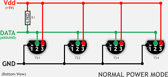
It's possible to put all the temperature sensors on one wire because each one has a unique address. This will be explained more later on.
Arduino Software
There are two main elements to the Arduino Software, the temperature sensors, and the Bluetooth module.
Temperature Sensors
The DS18B20 temperature sensor is an electronic thermometer with a high accuracy. Multiple thermometers can be connected on the same wire because every one has it's own internal address. More information about them can be found [HERE.] For the Arduino to be able to talk to the temperature sensors there unique addresses must be know. To do this follow the instructions found [HERE.] These unique addresses will be put into the code, so make a note of them.
HM-10 Bluetooth Module
The HM-10 module works by talking to the Arduino over a serial connection. While the hardware serial port on the Arduino could be used, this would make it very difficult to program the Arduino or use the serial monitor. To avoid this we will use SoftwareSerial to create a new virtual serial port to talk to the HM-10. After the hardware is set up the first thing that should be done is to check that the HM-10 is working. We can do this using a serial communication sketch found [/HM-10%20Bluetooth%20LE#Setting%20Up%20the%20HM-10 HERE], and AT commands. Run the sketch and then open the serial monitor. Make sure that the serial monitor is set to both New Line (NL) and Carriage Return (CR). Type in AT and you should receive an OK back. If you do not get an OK there is something wrong with the HM-10, double check the wiring, and make sure that the Arduino is in 3.3 V logic mode. Then type in AT+PIN, this will send back the pin that you will need when pairing with the HM-10 from another device. If you would like you can set this to a new more secure pin by sending AT+PIN<yourPin>. In addition AT+HELP will bring up a list of all the AT Commands you can use. It should be noted that unlike normal AT commands these to not require the “?” or “=” identifier.
Bluetooth Temperature Sketch
The general framework of the sketch is as follows:
- Bring in needed libraries
-There are a few none standard libraries that must be imported
- Create our OneWire communication line to talk to the temperature sensors
-This is where the devices addresses from the Temperature Sensor section should be put
- Setup: starts both the hardware and the software serial ports at a baud rate of 9600 bps, and initializes the temperature sensors.
- Loop: collects temperatures from each sensor in turn and sends it via software serial to the HM-10, where it's then passed to the Android App. Note the delay, this is to prevent data coming out of order to the Android app which could cause errors.
- CollectTemp routine: This reads in data from one of the temperature sensors and parses it into a form that can be sent byte by byte to the HM-10.
Note: The collectTemp routine breaks down the incoming temperature into three bytes. One byte for the sensor it came from, one for the sign of the temperature negative or positive, and one for the value itself. The reason for this is that serial communication happens byte by byte. A byte is a number between 0 and 255, or a signed number between -128 and 127. To allow for a wider range of temperatures the sign is removed and sent as a separate byte.
/*
  YourDuino Example: Bluetooth LE Temperature Reporting

  Description:
  Uses the HM-10 Bluetooth Low Energy module to enable an Arduino board to communicate temperatures over Bluetooth
  wireless to an Android app written in MIT App Inventor 2, running on an Android device.
  Get HM-10 Here: http://www.yourduino.com/sunshop/index.php?l=product_detail&p=529
  Get Temperature Sensors here: http://www.yourduino.com/sunshop/index.php?l=product_detail&p=134
  and the waterproof version here: http://yourduino.com/sunshop//index.php?l=product_detail&p=151
  Get the companion app:THESE NEED TO BE ADDED
  Get companion app sourcecode:
  Questions?    noah@yourduino.com


  Credit:
  This Arduino Code is Based Loosely on Serial_Sketch written by Martyn
  http://www.martyncurrey.com/hm-10-bluetooth-4ble-modules/
  and YourDuino Example: Multiple Temperature Sensors To 4x20 LCD
  https://arduinoinfo.mywikis.net/wiki/MultipleTemperatureSensorsToLCD

  Wiring:
  Set Arduino to 3.3V mode.

  DS18B20 Pinout (Left to Right, pins down, flat side toward you)
  - Left   = Ground
  - Center = Signal (Pin 10):  (with 3.3K to 4.7K resistor to +5 or 3.3 )
  - Right  = +5 or +3.3 V
  Note: All 4 temperature sensors should be attached to Pin 10

  HM-10 Pinout
  RX to pin 9 (Sofware TX)
  TX to pin 8 (Sofware RX)
  Vcc to 5 V
  Gnd to Gnd

*/

/*-----( Import needed libraries )-----*/
// Get 1-wire Library here: http://www.pjrc.com/teensy/td_libs_OneWire.html
#include <OneWire.h>
//Get DallasTemperature Library here:  http://milesburton.com/Main_Page?title=Dallas_Temperature_Control_Library
#include <DallasTemperature.h>
// Wire (I2C) Library
#include <Wire.h>
//Sofware Serial Library
#include <SoftwareSerial.h>

/*-----( Declare Constants and Pin Numbers )-----*/
#define LEDPIN 13 // Pin on Arduino board to which status LED is connected
#define READ_RATE 200 // How often a temperature is sent
#define FLASH_RATE 100 // The on/off period in milliseconds, for the LED Flash status feedback
#define TXPIN 8 //Connected to TX on HM-10
#define RXPIN 9 //Connected to RX on HM-10
// Data wire is plugged into port 10 on the Arduino (can be changed)
#define ONE_WIRE_BUS 10    // NOTE: No ";" on #define
// Create software serial instance
SoftwareSerial BTserial(8, 9);
/*-----( Declare objects )-----*/
// Setup a oneWire instance to communicate with any OneWire devices
// (not just Maxim/Dallas temperature ICs)
OneWire oneWire(ONE_WIRE_BUS);

// Pass address of our oneWire instance to Dallas Temperature.
DallasTemperature sensors(&oneWire);

/*-----( Declare Variables )-----*/
// Assign the addresses of your 1-Wire temp sensors.
// See the tutorial on how to obtain these addresses:
// https://arduinoinfo.mywikis.net/wiki/Brick-Temperature-DS18B20#Read%20individual

// WP 1
DeviceAddress Probe01 = { 0x28, 0xC6, 0xE1, 0x49, 0x04, 0x00, 0x00, 0xC9 };
DeviceAddress Probe02 = { 0x28, 0xDE, 0xC0, 0x2A, 0x04, 0x00, 0x00, 0x1E };
DeviceAddress Probe03 = { 0x28, 0xC1, 0xFA, 0x64, 0x08, 0x00, 0x00, 0x16 };
DeviceAddress Probe04 = { 0x28, 0xFF, 0x16, 0x30, 0xA2, 0x15, 0x04, 0x2B };

// Declarations
byte cmd;
byte sensor;
byte sign;
byte value;

// Initialization
void setup() {
  //------- Initialize the Temperature measurement library--------------
  sensors.begin();
  // set the resolution to 10 bit (Can be 9 to 12 bits .. lower is faster)
  sensors.setResolution(Probe01, 10);
  sensors.setResolution(Probe02, 10);
  sensors.setResolution(Probe03, 10);
  sensors.setResolution(Probe04, 10);

  pinMode(LEDPIN, OUTPUT);  // pin 13 (on-board LED) as OUTPUT
  digitalWrite(LEDPIN, LOW);
  Serial.begin(9600);       // start serial communication at 9600bps
  Serial.print("Sketch:   ");
  Serial.println(__FILE__);
  Serial.print("Uploaded: ");
  Serial.println(__DATE__);
  Serial.println(" ");
  BTserial.begin(9600);  //start software serial at 9600bps
  Serial.println("BTserial started at 9600");
}


// Arduino Execution Loop
void loop() {

  collectTemp(Probe01); //Collect data
  BTserial.write(sensor); //Send data to Bluetooth module
  BTserial.write(sign);
  BTserial.write(value);
  delay(READ_RATE); //wait to prevent data mixing

  collectTemp(Probe02); //Collect data
  BTserial.write(sensor); //Send data to Bluetooth module
  BTserial.write(sign);
  BTserial.write(value);
  delay(READ_RATE); //wait to prevent data mixing

  collectTemp(Probe03); //Collect data
  BTserial.write(sensor);//Send data to Bluetooth module
  BTserial.write(sign);
  BTserial.write(value);
  delay(READ_RATE); //wait to prevent data mixing

  collectTemp(Probe04); //Collect data
  BTserial.write(sensor); //Send data to Bluetooth module
  BTserial.write(sign);
  BTserial.write(value);
  delay(READ_RATE); // wait to prevent data mixing
}

// Support routines

//Flashes onboard LED n number of times
void flashLED (int n) {
  // Flash the LED n times, to provide an on board status indicator
  for (int i = 1; i <= n; i++) {
    digitalWrite (LEDPIN, HIGH);
    delay (FLASH_RATE);
    digitalWrite (LEDPIN, LOW);
    delay(FLASH_RATE);
  };
  return;
}

//Collects data from temperatuer sensors
void collectTemp(DeviceAddress probe)
{
  sensors.requestTemperatures();//send the command to get temperatures
  float temp; //Create local variable for temperature
  temp = sensors.getTempC(probe);//bring in the temperature from probe
  if (temp == -127.00) // Measurement failed or no device found
  {
    sensor = 0; //Set values to error mode
    sign = 0;
    value = 0;
  }
  else
  {

    temp = DallasTemperature::toFahrenheit(temp); // convert from C to F
    if (probe == Probe01)// set sensor byte to correct sensor
    {
      sensor = 1;
      Serial.println("Sensor1");
    }
    if (probe == Probe02)
    {
      sensor = 2;
            Serial.println("Sensor2");
    }
    if (probe == Probe03)
    {
      sensor = 3;
            Serial.println("Sensor3");
    }
    if (probe == Probe04)
    {
      sensor = 4;
            Serial.println("Sensor4");
    }
    if (temp >= 0) //if the temperature is positive
    {
      sign = 1;// set the sign byte to positive
            Serial.println("Positive");
    }
    if (temp < 0)//if the temperature is negative
    {
      sign = 0; // set the sign byte to negative
            Serial.println("Negative");
    }
    temp = abs(temp); //take the absolute value of the temperature
    value = round(temp); //round the temperature to the nearest intiger and set the value byte
  }
}
Android App
In order to view the Bluetooth data a smartphone needs an app that can interpret incoming data and show it to the user. This app also must handle finding and pairing with a Bluetooth device, in this case the HM-10. The .apk is the finished version of the app ready to be installed on a phone. The .aia is a project file for App Inventor 2- [/file/detail/BT_LE_Temperature.apk Details]
- [/file/view/BT_LE_Temperature.apk/618990883/BT_LE_Temperature.apk Download]
- 2 MB
- [/file/detail/BT_LE_Temperature.aia Details]
- [/file/view/BT_LE_Temperature.aia/618991093/BT_LE_Temperature.aia Download]
- 306 KB
MIT's App Inventor 2
MIT's App Inventor 2 allows for the easy creation of fairly powerful android apps. It uses a drag and drop programming interface very similar to scratch, as well as having a window for laying out an apps user interface. One of the best features of App Inventor is the ability to link a smartphone to it. This allows the app to run on your phone as you write your code, allowing you to debug and troubleshoot in real-time. Some intro level tutorials are [HERE], it's strongly encouraged that you work through them to get a feel for App Inventor before you try to move on to the Bluetooth temperature app.
Bluetooth Temperature App
This app has two jobs. The first is to connect to the HM-10, and the second is to talk to the HM-10 and get values in from temperature sensors.
Setting Up
The first step is to open the app inventor and create a new project. You should see a blank screen template with toolbars on the left and right. We now need to add in an extension to communicate over Bluetooth LE. There are a few extensions that MIT has provided, a BTLE extension is one of them. Go to the ling [HERE] and download the BluetoothLE extension. Then in the app inventor project window go down the the Extensions tab at the very bottom of the left side toolbar. Click import extension and follow the prompts to upload BluetoothLE. Now click and drag BluetoothLE onto the blank canvas. You should see it pop up in the Non-Visible Components area.
Now add the timers. Timers are under sensors, drag two onto the canvas and drop them. They should show up as timer1 and timer2. Now click on one at the bottom of the canvas. On the components toolbar to the right, you should see the clock highlighted. Click Rename and name this Refresh_Clock. The refresh clock is used sort of like Loop in Arduino programming. It makes the app go and fetch the temperatures every 300 milliseconds. Further to the right in the Properties toolbar check the TimerAlwaysFires box (this makes sure that the timer will go off even if the app is running in the background), also check the TimerEnabled Box. Finally set the TimerInterval to 300. There is no reason it has to be 300 milliseconds, but it is fast enough, but doesn't cause issues with data starting mix. The second clock should be named BuffTimer1, and set to 100 milliseconds. Uncheck the Enabled button, this timer will be enabled in the software when it's needed. This timer will be used to display messages for only a short period of time.
Next add a notifier from the user interface tab of the Pallet toolbar. This can be used to pop up error messages.
App Inventor Companion
The first step is to install the app inventor. You can can find it in the Play Store [HERE], or simply scan this QR Code. 
Once you have the app installed open it up and click Scan QR code. Then go to app inventor on your computer and click connect on the uppermost toolbar. Click the AI companion button and a QR Code will be popped up for you to scan. The AI companion tool is not perfect, particularly when changing screen elements around it sometimes crashes. Usual this cause the app to hang. To reconnect close the companion app and restart it. Then in app inventor go back to the connect tab. Click reset connection and then hit AI companion to be issued a new QR code to connect.
User Interface and Layout
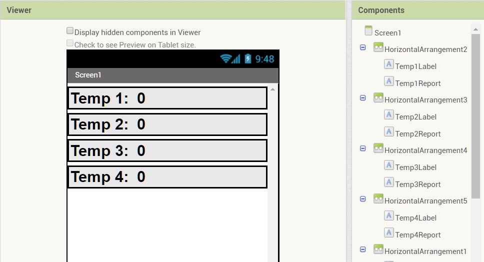
To create the user interface start by going to the Layout tab of the Pallet toolbar. Drag and drop 4 horizontal arrangement blocks onto the blank canvas. Click on each in turn and in the Properties toolbar to the far right set the width to Fill Parent. This will make this horizontal arrangement fill the width of whatever screen it is on, this is helpful because it makes the app work on more devices. Next go to the User Interface tab and drag and drop two labels in each. For each one use the Properties toolbar to set the font to bold size 28. Also set the width to Fill Parent. Next set the text of of the first label in each horizontal arrangement to Temp1, Temp2, etc. These are set in the Properties toolbar. In addition these labels should be named using the Components toolbar. Name each one Temp1Label, Temp2Label, etc. Now do the same to the second label in each, setting the text to 0 in each one. Name each one Temp1Report, Temp2Report, etc. It's very important to clearly label the on screen components, as it will make creating the code much easier. When you are done it should look like this:
Now add the buttons to switch between Fahrenheit and Celsius. Create another horizontal arrangement that is set to Fill Parent. From the User Interface tab add two buttons. Set the font for both to bold and 28 Pnt. and set their widths to Fill Parent. Set the text to Fahrenheit and Celsius respectively and the names to ButtonF and ButtonC.
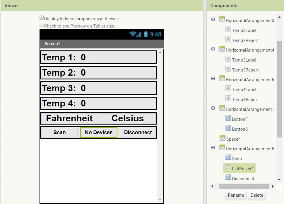
Next up is adding the buttons to allow us to connect to a particular Bluetooth device. A scan button will look around for available Bluetooth devices. A ListPicker will allow us to pick the correct device from those available. Finally a Disconnect button will sever the Bluetooth Connection. Create another horizontal arrangement that is set to Fill parent. From the User Interface tab add a Button, a ListPicker, and then another Button. Set the font for all to 16 and bold. For the first button set the text to Scan and name the button Scan as well. For the ListPicker set the text to No Devices and leave the name ListPicker1. The second button set the text to Disconnect and the name to Disconnect. When you are done it should look like this:
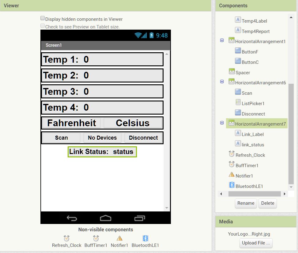
Finally another horizontal arrangement is added to create a status notifier for the Bluetooth. Put two labels in this arrangement. Font size 16, bold. Name the first Link_Label and set its text to “Link Status:”. Name the second link_status, and set its text to “status”.
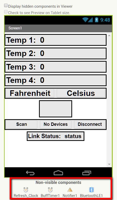
The finished layout should look like this:
Creating Code Blocks
The code in app inventor is written using a drag and drop interface that is very similar to Scratch. To the left in the blocks toolbar are all of the elements of the user interface as well as some basic elements; Control, Logic, Math, etc. Clicking on one of these elements brings up a menu of all the related blocks. It should be noted that with a large program, it may take a few seconds between clicking an element and the menu coming up.
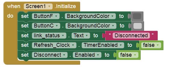
The code is created in order of how the app will be used. We start with the Screen.Initalize Block.
To start click on the Screen1 element in the Blocks toolbar. In the menu that opens scroll down until you see the Screen1.Initialize block. This block is called when the app starts and then does everything inside of it. Grab the block and drag it into the Viewer. Next go into the Blocks toolbar and click on ButtonF. Find the set background color block and drag it into the viewer. Clip it into the Screen.Initialize Block. You should hear a click. Next go to the Color element in the Blocks toolbar. Drag dark gray into the View and clip it to the set background color block. This will now set the Fahrenheit button's background to dark gray.
Next we want to set the Celsius button to light gray. We could do this by repeating all the same steps as we did for the Fahrenheit button, but there is an easier way to do this. If we click on the set background color block we already have, it will be selected. Then simply copy and paste. Now click where it says ButtonF and a drop down with all the buttons will appear. Set this to ButtonC instead. Do the same for the dark gray color. Set this to light gray. While were doing things with buttons lets set the Disconnect button to Disabled. To do this past another version of the set background color block. Now change the button in question to the Disconnect button. If we click where it says background color and it will drop down all the things we change about a button. Set it to Enabled. Then click the Logic element in the Blocks toolbar. Drag the False block to set enabled and clip it to it. This sets the Disconnect button to be disabled. Copying as pasting is very helpful for quickly creating code.
Next up we go to the link_status element in the Blocks toolbar, grab the set text block from it and clip in in, then go to the Text element and grab an empty text block. Clip it in and then write “Disconnected” in it. Now go to the Refresh_Clock element and grab the set time enabled block. Set this to False by grabbing a false block from the Logic element. Alternatively you can copy and paste the false statement attached to the Disconnect enabled block.
Code Blocks
From here on in the code will be given by showing the block and then explaining what it does. For the most part the blocks are in the order of how they will run, but this is only for our convenience.
This block activates when the Scan button is clicked. It calls the Bluetooth on the phone to search for available Bluetooth devices.
This block is activated when the scan for devices finds a device. The set ListPicker1.ElementsFromString block reads in the device list and creates a menu. The text of the menu button is changed from “No Device” (what we set it to start with) to “Choose Device”.

The next section of this block sets the text of the link status to “Trying to connect to <device>” note the join function used, this simply joins two pieces of text together in order. Finally the BluetoothLE1.ConnectwithAddress creates a connection with the HM-10 Module.
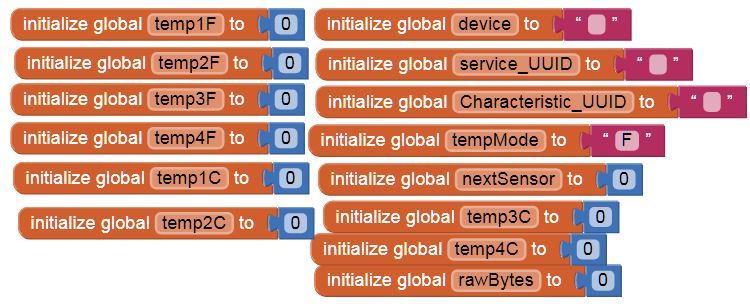
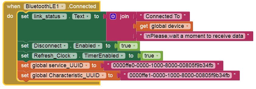
This block gets called when the BluetoothLE1 detects that it has successfully connected with a device, it sets the link_status text to “Connected To <device> Please, wait a moment to receive data”. The next block enables the disconnect button, now that there is something to disconnect from. Refresh_Clock.TimerEndabled set to true turns on the refresh clock. In App Inventor a clock that is enabled will “go off” every interval, and an event can be activated by the clock “going off”. Finally the code sets two more global variables service_UUID and characteristic_UUID to there correct values. These UUIDs (Unique Unit Identifier) are always the same for the HM-10. Note that they are not the same, service us ffe0 and characteristic is ffe1. These variables must be created and initialized just like the device variable.
This block is called when the Disconnect button is pressed. It sets the link_status text to “Disconnected” and then disconnects the Bluetooth link.
This block is called with the Celsius button is clicked. It sets the colors of the buttons to show the user that it's in Celsius mode, and then changes the global variable tempMode to C. This is another global variable that must be created and initialized to a value.
This is the same as the above, but for the Fahrenheit button.
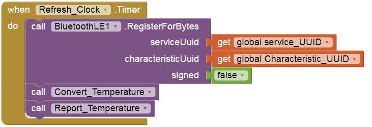
This is the clock block mentioned in the BluetoothLE1.Connected block. When the Refresh_Clock goes off every 300 milliseconds it will call this block. The first thing it does is the call the BluetoothLE1.RegisterForBytes function. This looks for bytes coming in over the Bluetooth and calls another block when it sees them. The signed set to false means that it is looking for an unsigned byte. The next two blocks call functions which will be covered later.
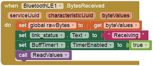
This is the block that is called when BluetoothLE1.RegisterForBytes sees bytes coming in over the Bluetooth. The three variables seen in the BytesReceived block are local variables that the block creates and sets the value of. The service and characteristic variables have already been discussed. ByteValues is a space seperated list of all the bytes availabe. Inside the Block It first sets a global variable rawBytes (that must be created) to byteValues. link_status is set to “Receiving” and the bufftimer1 is enabled. The bufftimer1 is used to set the link_status back to “Waiting for data”. Otherwise once it received data once it would always say “Receiving, true or not. It then calls the function ReadValues, which is shown later.
BuffTimer1 is turned on when link_status is set to “Receiving”. When the bufftimer1 goes off it sets the link_status back to “Waiting For Data” and then turns off the BuffTimer1, otherwise it would continue to reset the link_status.
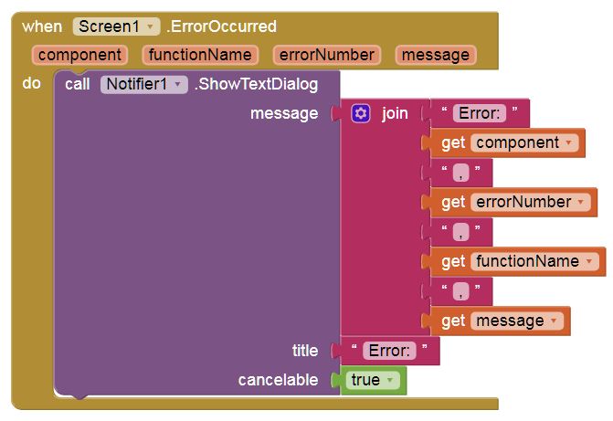
This block is called when the app detects and internal error. The local variables are created and set to values by the block. The notifier is used to pop up an error message detailing what the error was. Note the cancelable function being set to true this is important as otherwise there is no way to get rid of error messages without closing the app.
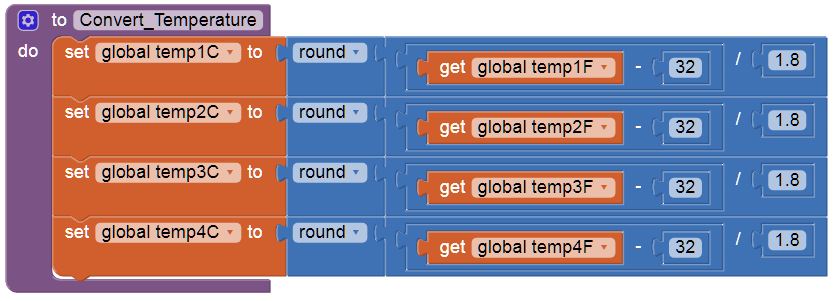
This block is a function in this case called by the refresh clock. To create a new function go to the Function element in the Blocks toolbar. It takes the global variables for the temperatures in Fahrenheit and converts them to Celsius. Note that these global variables must be created previously.
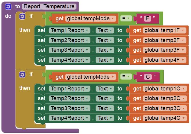
This function is also called by the refresh clock. It sets the temperature report labels to the correct temperatures depending on if it is in Fahrenheit or Celsius mode.
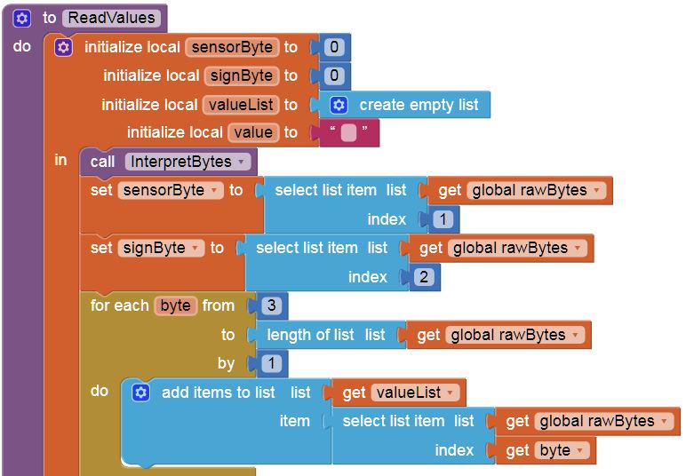
The Arduino sketch takes the temperatures from each sensor and creates a package with it. This package is always of the form (<sensor number> <temperature sign> <value digit one> <value digit two> etc.). For example the temperature -15 degrees from temperature sensor one would be sent as (1 0 1 5) and 102 degrees from temperature sensor three would be sent as (3 1 1 0 2). The next two blocks read in the sensor byte and the sign byte into local variables, these will be used later on.
The for each byte block is an iterative statement starting at element three (the first digit of the value) and going to the end of the rawBytes list, it creates a new list called valueList with these values. Basically what this does is creates a new list that just has the temperature value. For example if the incoming data was 102 degrees from temperature sensor 3, valueList would now read (1 0 2)
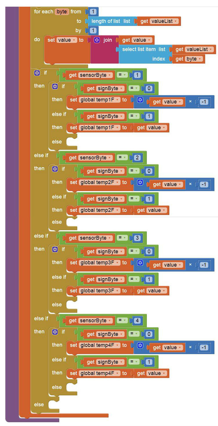
This is the second part of the ReadValues function. The first part here is another iterative operation, for each item in the list it takes that item and joins it to a new variable called value. In other words it takes the list (1 0 2) and simple creates a variable value that is equal to one hundred and two. The next section if a four part if, else if statement. Just like with adding multiple local variables, to create multiple else ifs click the blue gear in the upper left hand corner It starts by checking the sensor byte, so it knows which temperature sensor the value came from. Then it checks the sign byte and if it is negative it multiplies the value by -1 and sets that temperature variable to the value, if its not negative it simply sets that temperature variable to to the value.
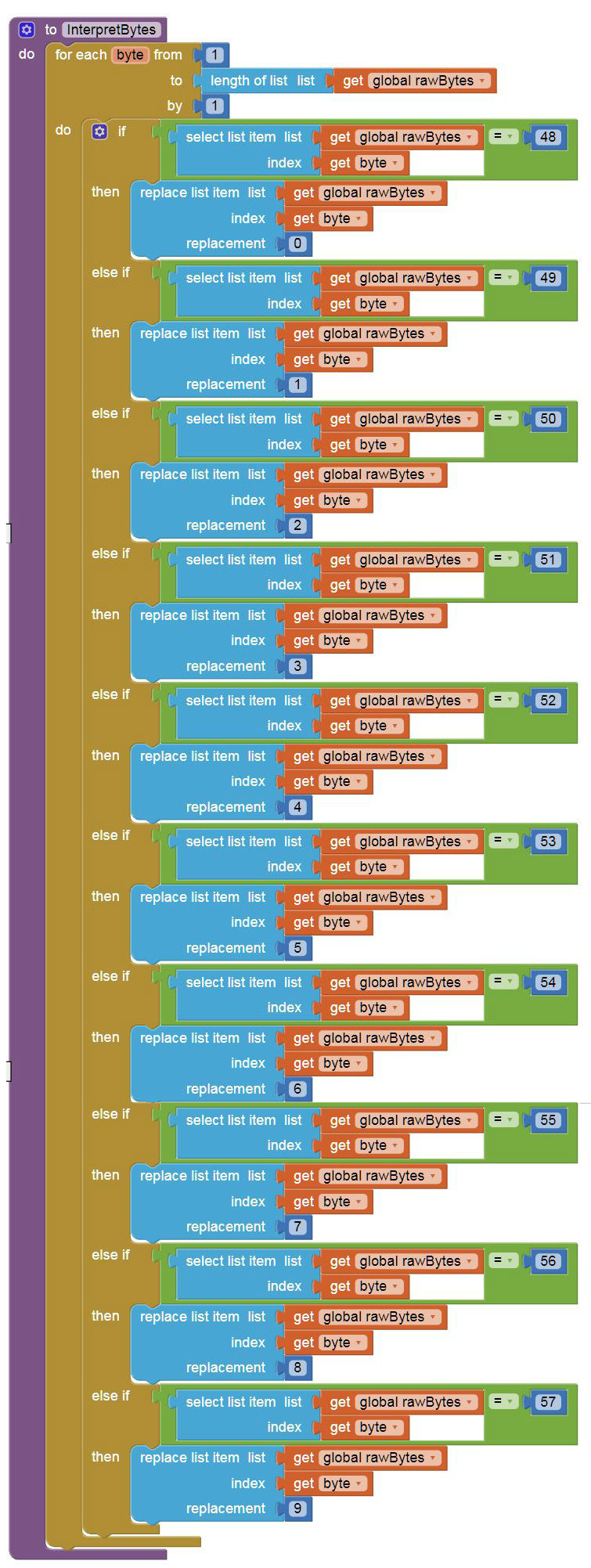
The final function is the InterpretBytes function called at the beginning of ReadValues. When data is sent through the Bluetooth link it shifts them from there normal values to ascii. This means that if the Arduino sends a 0 it arrives as the ascii value for 0 which happens to be 48. This function is another iterative loop that takes every item in the rawBytes list and converts it from ascii to normal characters.
Putting it all Together
The final step is to put all the pieces together. Load the Arduino Code and you should see that the small red status light on the HM-10 module blinks. This means that it is actively looking for a device to pair with. Next go to android Bluetooth settings. You should see a Bluetooth device called MLT-BT05. Click on it and it should ask for a pin. This pin defaults to 123456. Once it is set up on the phone start up the app using the App Inventor companion app. First press scan, then when the button next to it changes to “Choose Device” click it and pick the HM-10. The link status should briefly say “Connecting to Device <DeviceAdress>, Please wait a moment to receive data” and then the temperatures should start coming in. Try clicking the F and C buttons and make sure that it properly converts and displays the temperature in Fahrenheit and Celsius.
