YourDuinoEngStarter-SPANISH
YOURDUINO - MICROORDENADOR INGENIERÍA SET (Y Cómo se hace para el BASIC KIT)
AHORA: Todos los kits YourDuino vienen con la YourDuino RoboRED Microcomputer Board (click)

Por favor enviar comentarios, críticas, sugerencias y preguntas a: terry@yourduino.com
Este documento How-To coincide con el YourDuino Ingeniería Starter Set (enlace) y todos sus componentes. Este Set añade 4 nuevos componentes (parte superior derecha 3 compartimentos en la foto de arriba) a la YourDuino Básica Starter Set (enlace). Lecciones 1-8 Aplicar sobre el kit básico también.
Este Cómo documento está disponible en formato PDF
- [/file/detail/arduino-info%20-%20YourDuinoEngStarter.pdf Details]
- [/file/view/arduino-info%20-%20YourDuinoEngStarter.pdf/547160420/arduino-info%20-%20YourDuinoEngStarter.pdf Download]
- 11 MB
MENÚ
[/YourDuinoStarter#%20LI Introducción]
[/YourDuinoEngStarter#%20L1 Lección 1: Introducción]
- Instalación de software y pruebas de Arduino
[/YourDuino%20Ing%20arranque#%20L2 Lección 2: Software Tiempo y escritura Arduino Sketches]
- Aprender a escribir software de Sketches
[/YourDuinoEngStarter#%20L3 Lección 3: Hardware: Hacer conexiones]
- Conexión Breadboards, Alambres y LEDs
[/YourDuinoEngStarter#%20L4 Lección 4: Componentes: Aprendiendo sobre Dispositivos de entrada]
- Conexión de un Switch & Fotorresistor
[/YourDuinoEngStarter#%20L5 Lección 5: Componentes: Entradas analógicas]
- Conexión del potenciómetro y el Fotorresistor
[/YourDuinoEngStarter#%20L6 Lección 6: Toma de decisiones y la creación de sistemas de trabajo]
- Realización de un controlador de iluminación
[/YourDuinoEngStarter#%20L7 Lección 7: Salida analógica: Atenuación Luces y hacer sonidos]
- Realización de una toma de regulador y Multicolor Suena con Arduino
[/YourDuinoEngStarter#%20L8 Lección 8: Señales: Hablando con dispositivos más complejos]
- Ejecución de un servo y medición de la temperatura
[/YourDuinoEngStarter#%20L9 Lección 9: El Juego de Ingeniería dispositivos añadido]
- Sensor de distancia por ultrasonidos
- Motor de pasos y tarjeta driver
- 2.4 Ghz Radio Transceptor
- Voltímetro Digital Mini
MENU
[/YourDuinoStarter#LI Introduction]
[/YourDuinoEngStarter#L1 Lesson 1: Getting Started]
- Installing software & Testing Arduino
[/YourDuinoEngStarter#L2 Lesson 2: Software Time & Writing Arduino Sketches]
- Learning to Write Software Sketches
[/YourDuinoEngStarter#L3 Lesson 3: Hardware: Making Connections]
- Connecting Breadboards, Wires and LEDs
[/YourDuinoEngStarter#L4 Lesson 4: Components: Learning About Input Devices]
- Connecting a Switch & Photoresistor
[/YourDuinoEngStarter#L5 Lesson 5: Components: Analog Inputs]
- Connecting the Potentiometer & the Photoresistor
[/YourDuinoEngStarter#L6 Lesson 6: Making Decisions & Creating Working Systems]
- Making a Lighting Controller
[/YourDuinoEngStarter#L7 Lesson 7: Analog Output: Dimming Lights & Making Sounds]
- Making a Multi-colored Dimmer & Making Sounds with Arduino
[/YourDuinoEngStarter#L8 Lesson 8: Signals: Talking to More Complex Devices]
- Running a Servo & Measuring Temperature
[/YourDuinoEngStarter#L9 Lesson 9: The Engineering Set added devices]
- Ultrasonic Distance Sensor
- Stepper Motor and Driver board
- 2.4 Ghz Radio Transceiver
- Mini Digital Voltmeter
INTRODUCTION
This manual will show you how to use each of the components in the kit, and give you software Sketch examples for each one. Then you can combine some components to make examples of Automatic Systems such as a lighting controller.
  You're probably here because you're interested in MAKING things with Arduino. The first questions:
- What can you do with a MicroComputer like Arduino?
- How do you get started?
What Can You Do with Arduino?? See this link (To be Updated!)
To get started, we think you need 3 things:
- Clear Information
- Practical, Low-Cost hardware to learn with
- Detailed How-To DO IT.
Making things with Electronics and MicroComputers is different than Woodworking or Metalworking. There are a couple of little problems: Uh Oh!
- ===Electricity is INVISIBLE !===
- ===AND, Software is INVISIBLE !===
Not to worry! We will show you the ways to make these powerful tools Visible so you can use them.
LESSON 1: GETTING STARTED
The Arduino "IDE" software looks virtually the same on Windows, MAC or Linux, but the Installation procedures are different. Below, you can pick which one you need.

  Oh.. "What's this IDE thing all about anyway" ?? The Arduino Integrated Development Environment
 (WikiPedia) is the software you use on your computer to write software Sketches and then upload and run them on the YourDuino hardware. The IDE is like a word processor for writing software.

  Now, go to the official Arduino site to download and install the software for your operating system:
- [/ArduinoInstall-MAC MAC Installation]
- [/ArduinoInstall-WIN WINDOWS Installation]
- Linux Installation
After Installation, or if your board is already installed, continue here:
 CHECK OUT THE NEW YourDuino RoboRED:

The new YourDuino RoboRED is now used in these Starter Sets. Near the upper left is the PWR LED which should light up whenever the board is plugged into a USB connection, or has power from an external power supply.
  At the upper left there are two added red LEDs which will blink when a software sketch is being downloaded to the board, or other data is being transferred over USB.
  In the center is a red LED which is internally connected to pin 13 through a current-limiting resistor. It should blink after you load the example BLINK software sketch. The colored 3-pin connectors on every I/O Pin make it easy to connect many input and output devices. Vcc(+5V) pins and (Ground) pins with every I/O pin are good for connections to breadboards etc.
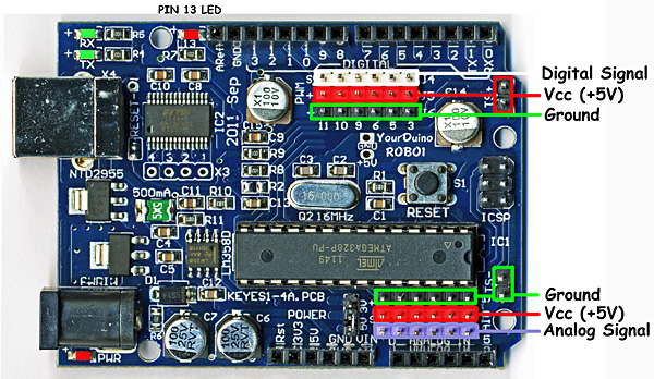 CHECK OUT THE YourDuinoRobo1:

NOTE: This version was used in earlier YourDuino Kits and is here for reference if you have one of these. On the right, let's look at some of the features of the Robo1 board as used in these Starter Sets. At the lower left is the PWR LED which should light up whenever the board is plugged into a USB connection, or has power from an external power supply.
  At the upper left there are two green LEDs which will blink when a software sketch is being downloaded to the board, or other data is being transferred over USB.
  At the top is a red LED which is internally connected to pin 13 through a current-limiting resistor. It should blink after you load the example BLINK software sketch. The colored 3-pin connectors make it easy to connect many input and output devices. The Vcc(+5V) pins at upper right and the (Ground) pins at the lower right are good for connections to breadboard etc.
(FOR ALL OF US, NOW: MAC, WINDOWS, LINUX):
RUN THE ARDUINO "IDE" SOFTWARE:
You should have followed the IDE Installation for your PC/MAC Operating System and now you've got your YourDuino plugged in and running. The POWER "ON" LED is on, right? You have successfully UPLOADED the "Blink" Sketch? And the "13" LED is blinking? (This may be a little different for the various YourDuino versions and the '13' LED may or may not blink now).

  Soon we'll start connecting the things in the Starter Set, but first we'll use that built-in Pin 13 LED to get started.
LESSON 2: SOFTWARE TIME & WRITING ARDUINO SKETCHES
Let's take a little while to get used to writing Arduino Software, then we'll come back and start connecting your Starter kit parts and making more interesting things. We will give you software examples for each of the devices in the Starter Set.

   On your desktop you should now have the Arduino ICON like this:
|
|
| external image Arduino-Icon1-68.jpg |

 Click on it, if you haven't already, and you should see the "Arduino IDE Window" pop up like this:


  You'll use this IDE (Integrated Development Environment) to make Software VISIBLE! With it you will develop your own software to make Arduino into what you want it to be.

FIRST, YOU MUST SET THE CORRECT BOARD TYPE AND SERIAL PORT
BOARD: In the Arduino IDE top menu click <Tools> and then <Board>. You will see a drop-down menu that looks like this (left).
NOTE: For the YourDuino RoboRED in all current kits, pick "Arduino UNO". For the older YourDuinoRobo1 click Arduino Duemilanove. (Same for PC and MAC)
SERIAL PORT: Now click <Tools> and then <Serial Port>. On the PC There will usually be only one choice. But you may have COM1 and then some higher number which is Arduino.


On the MAC, see the example on the right. Pick the entry that has both "tty" and "usbserial" in it.
OK, you're ready to upload software sketches to your YourDuino or Arduino!
SKETCHES:
The visible text of an Arduino software program is called a SKETCH. But the Sketch becomes alive when you upload it to your Arduino. Let's walk through Editing a Sketch and Verifying it and Uploading it:

 Click on FILE and then move your mouse (slowly.. It's Fussy!) over EXAMPLES to BASICS and then to BLINK  so it looks like this (On the right):
 And CLICK. There are lots of examples that come with the free Arduino software system, and we will look at some of them later, as well as make our own very soon.

  A new IDE window should pop up and look like this:

  Wow.. A bunch of new stuff.

  Let's slow down and "Watch Closely Now"!

  Notice that a lot of the text is GRAY. All of that is just "Comments" for you to read to help understand the Sketch. When you write software, you should also use "Comments" to explain to others what you are doing. (Arduino itself totally ignores these comments).

  Now, let's go through Editing software, Verifying it, and Uploading it to see Arduino DO it. We will use the YourDuino version of Blink: YourDuinoStarter_Blink . Click on the link to see it's page.
  Now, highlight all the code (in the gray area) , do <Ctrl>C to Copy, in the IDE, the New button to get a blank page and do <ctrl>V to Paste it in. Click Verify to make sure it's OK. You should see "Compiling Sketch" and then "Compiling Done". Now look at the sketch in detail. Take some time to read it slowly.


STRUCTURE OF ARDUINO SOFTWARE:
Every Arduino Software Sketch has two main parts:
- SETUP - Runs Once at the beginning
- LOOP - Runs over and over again, forever
You will read a LOT of program "Code" that other people wrote, in the future. You HAVE to "Watch Closely Now" and really see the details. Read the YourDuinoStarter_Blink example through carefully, a couple of times. Note the colored special words that are Instructions . These are unique words that tell Arduino what to do. They have to be spelled perfectly!
What SETUP does: Tells Arduino about things that need to be done once. Arduino Digital Pins can be either INPUT or OUTPUT. You have to tell Arduino when a Pin will be used as an OUTPUT. In this example, there is one line that tells Arduino that Pin 13 must be an OUTPUT.
![]()
Note the COLOR of the lettering. The Arduino IDE changes the color of words as it recognizes them as special instructions. Let's mess with them:
pinMode: Note that when Instructions are two words run together, like pinMode, the beginning of the SECOND word is Capitalized. Change the Capital "M" to "m". Note the color changes to black. Hmmm. Click the VERIFY ![]() button.
button.
You will get an ERROR message: ![]()
Fussy, Fussy, Fussy! Yep, every letter has to be correct and also correct upper or lower case.
Change it back. Check the color. Click Verify again. OK??
What LOOP does: Loop contains all the active parts of your Sketch that continue to run after SETUP is finished. It will run over and over again, forever, or until you stop it or power down.
What does VERIFY do??![]()
A LOT! More details later, but Verify is a program in your main computer that goes through every Instruction in your Sketch (Ignoring "Comments") and checks it against the list of valid Instructions, and checks that the structure and sequence of the statements in the Sketch are correct. Fussy, Fussy! If they're OK, then it "compiles" or "translates" the sketch into the machine code that Arduino actually runs on. It saves that 'ready-to-run' code for you to Upload to Arduino and run. Other systems would call this process "Make" or "Compile".
What does UPLOAD do??![]()
First, Upload runs Verify to check and compile your program. Then it communicates to your Arduino over the USB connection, resets the Arduino chip, and talks to software already on Arduino (called the BOOTLOADER(W)) to load your new program into the Arduino's memory. Then it restarts Arduino and your program runs it's SETUP section and then repeats the LOOP section.
[NOTE: The (W) Means this is a Wikipedia link.]
Start Making Changes:
Ok, let's make a few changes to the  YourDuinoStarter_Blink program:


  The LOOP section of your program does all the instructions in the section, and then "loops" back to the top and starts it again, over and over.

 NOTE: the "Brackets" { and }

  Notice that the beginning and end of the section is "inside brackets". You will see many sections of bigger programs that are grouped by these "brackets".

  Now, let's look in detail at the instructions:

Instruction: digitalWrite
This instruction sets an OUTPUT PIN to either HIGH (connects it to +5 V) or LOW (Connects it to GND).

  Remember: HIGH = 1 = ON = 5 Volts and LOW = 0 = OFF = 0.0 Volts

  So, the first line in LOOP sets PIN 13 to HIGH. This means Pin 13 is connected to +5 Volts, and current flows through the resistor and LED that are already connected to pin 13. The LED lights up.
Instruction: delay
The delay instruction just waits for a period of time. The VALUE used with delay is in Milliseconds (1/1000 second). So delay(1000); waits for 1000/1000 seconds (1 second). We'll change that soon.

 NOTE: the ";" (Semi-Colon)

  Notice that every instruction is followed by the character " ; " which is like a period that tells the end of a sentence. Run-on sentences will make you stay after school to fix your error messages!

 Change the delay so that the LED blinks differently:

  Time to mess about and try some things! Maybe we'll break it. Then we'll fix it..

  Suggestion: Save your own version of BLINK so you can always go back to the original one. Go to File and Save As and call it something like MyBlink. This will go in your SKETCHBOOK where you'll save your own programs.

  Now go change the VALUE in a delay statement to change the way the LED blinks. Think about the 4 instructions in LOOP. What's happening??
- Turn the LED on. Wait and look at the LED.
- Turn the LED off. Wait and look at the dark.
So, let's change the ON time to be short. Maybe 50 Milliseconds. That's 1/20 of a second. Then try 10 milliseconds. The LED is only on 1/100 of the time. Can you still see it blink? How about 1 millisecond?
Each time you make a change, click Upload![]() which will first Verify and Compile your program and then send it to Arduino. Notice that each time you do this the LEDS that are marked "Tx" (Transmit) and "Rx" (receive) flash as your main computer communicates with your Arduino.
which will first Verify and Compile your program and then send it to Arduino. Notice that each time you do this the LEDS that are marked "Tx" (Transmit) and "Rx" (receive) flash as your main computer communicates with your Arduino.
Try some combinations of ON and OFF delay() times. Like ON 1000 and OFF 50.
Try making both ON and OFF times shorter and shorter. If you make the ON and OFF times short enough your eye will no longer see blinking, because of "Persistence of Vision"(W) which happens when there are more than about 25 blinks per second. So, hmmm.... if you make the LED be ON for 1/50 of a second and OFF for 1/50 of a second that should do it. So try 1000/50= 20 Milliseconds. Put 20 for both the ON and OFF times. What do you see?? How about 10 Milliseconds each? Depending on your personal eye's physiology, at some speed you will not see any more blinks. Young people can usually see faster blinks.
All right. You're the Programmer! You can save any of the sketches for use later on. Go to File>Sketchbook and you'll see them.
Next, we'll start hooking up the Electronics Parts in your Starter Set! And we'll give you example Software Sketches for each one of them.
LESSON 3: HARDWARE: MAKING CONNECTIONS
BREADBOARDS, WIRES, PINS, CABLE and ELECTRONICS COMPONENTS:
Arduino is great but sometimes connecting interesting things to it can be a pain. We tried to make it easier for you. We will use a BREADBOARD (W) for most connections.
The idea here is that wires and electronics parts like LEDs and RESISTORs have wire leads that can be plugged into the BREADBOARD and then easily be removed or changed. The holes in the BREADBOARD go down into little sockets with metal contacts.
Sections of the BREADBOARD have rows or columns that are all connected together, making it easy to have multiple things connected together.
Here's some detail of how the BREADBOARD that we use in this kit is organized:
external image BreadBoard-1.jpg
The Horizontal Rows have 5 holes (abcde) and (fghij) with sockets that are connected together. Any wires or parts that are plugged into one of these rows are connected together.
The Vertical Columns (+Red and -Blue) have the same connection running all the way down. We will use these to connect 5V on our YourDuino board to the +Red and to connect GND on our YourDuino board to -Blue. Then any time we need to connect to GND, we just plug a wire or part into the -Blue column, and any time we need to connect to 5V, we just plug a wire or part into the +Red column
Now let's look again at the YourDuinoRobo1 board and the new YourDuino RoboRED, and where we will make connections. Later we will look at the boards in a lot more detail, but for now let's just hook up a few things and make them work.
|
|
| YourDuinoRoboRED |
The first thing we want to do is connect GND on the board to a -Blue column on the breadboard and 5V on the board to a +Red column. Notice the pin connectors on the far right of the YourDuinoRobo1, labelled TS- (which is Ground) and TS+ (which is +5V). They are convenient to connect +5V and Ground to the breadboard. On the RoboRED you can use any of the VCC (+5V) and Ground pins in the long rows of 3-pin connectors.
We will orient the breadboard left-to-right so it can sit in front of the YourDuino board so we can easily make many connections and changes.
 So it will look something like this:
We will mainly use the upper +Red row and the bottom -Blue row. Often we think of these parallel lines as "Rails" like railroad rails. The top red rail is the "+5 Volt Rail" and the bottom blue rail is the "Ground Rail". "Voltage Rails" (W) is a common terminology in electronics.
How to THINK about Arduino:
We will use this picture to think about how we connect things to Arduino. It shows the +5V and Ground "Rails". (More about Diagrams later). 
What about wires? Locate the "40 pin flat cable" and the "Male-Male Pin Strip Connectors" in your kit.
To start we will connect the "5V Rail" to "5V" on the YourDuino board.
WIRES:
We will use the "40 pin flat cable" in your kit for wires. It looks like this:


  You can easily strip off one or more wires, or strip off a section to use as a cable. The ends of these wires are female connectors that can plug onto the connectors on the RoboRED or a "Sensor Shield". But what about the breadboard?? It needs a wire with a male end to plug into it. The pin strips (Right) are the answer. Your kit has 2 of these with 40 pins each. You can cut or snap off the number of pins you need. For now, snap/cut off about 6 single pins. It's easier to snap off just 1 pin if you grab it with a small pair of pliers of some kind. Or you can "cut" in between the pins with strong scissors or wire cutters.


  Here's the way this works:


|
|
| male pins (left) |

|
|
| female wire ends |

|
|
| 3-pin strip |

|
|
| 3-pin cable end |

You can make any combination of male or female cable ends of different widths.
 Now, let's connect your Breadboard to the YourDuino board. Unplug the USB cable before making any big changes!
Strip off 1 Blue wire and 1 Red wire from your flat cable. Run the Red wire from a +5 (TS+) pin on the YourDuino to the +Red Rail on the breadboard. Run the Blue wire from a GND (TS-) pin on the YourDuino to the -Blue Rail on the breadboard. Now it's easy to connect things to the 5V (+Red) Rail or the GND (-Blue) Rail. We show +5 and Gnd connected to the TS pins on the far right side of the Yourduino board.
 See the close-up photo here, and plug a 220 Ohm (Red-Red-Brown) resistor [TBD: Color Code] and a red LED (Long pin to the left) into the Breadboard as shown. (Use male-male pins where you need a male end to plug into the breadboard or YourDuino).
Now add a wire (Black is shown) from the same vertical strip as the LED to the GND Rail. Connect another wire (Green is shown) to the same vertical strip as the left end of the resistor, and use a pin to plug it into the YourDuino socket labelled 13.
We are Making CIRCUITS:
OK we need to stop for a minute and make sure we understand how the breadboard, the components and wires make up Circuits we want. A circuit has one continuous connection from a source of electricity, through some wires and circuit components, and back to the other terminal of the source. Let's follow what we did above:
  Start:

   1. WIRE from YourDuino Pin 13 TO 5-hole Vertical Strip 1 - (fghij) (Column 1, strip fghij)
  2.  5-hole Vertical Strip 1 - (fghij) TO Left end of 220 ohm Resistor
  3. Ri ght end of 220 Ohm Resistor TO 5-hole Vertical Strip 4 - (fghij) (Column 4, strip fghij)

   4.  5-hole Vertical Strip 4 - (fghij) TO Left (long) end of LED
   5. Right end of LED TO 5-hole vertical strip 6 - (fghij)
   6. 5-hole vertical strip 6 - (fghij) TO Ground Rail (Blue horizontal strip at bottom)
   7. WIRE from Ground Rail (Blue) TO YourDuino Ground pin

   OK, that's pretty laborious, but now TRACE the circuit through those parts. What if we said it more simply from now on, like:
   1. WIRE from Pin 13 to Strip1
   2. 220 Ohms resistor from Strip1 to Strip4
   3. LED from Strip4 (long lead) to Strip 6
   4. WIRE from Strip6 to GND Rail
   5. WIRE from GND Rail to YourDuino GND pin
Power Up and RUN:
Time to Power Up! Plug the USB cable from your computer into the YourDuino. Its PWR LED should come on. And the pin 13 LED should be blinking in the way you last programmed it. If necessary load the original GOBP (Good Old Blink Program!) and Upload it to YourDuino. Your setup should look like the photo on the right above. AND the LED you just wired up on your Breadboard should blink the same as the 13 LED on YourDuino. NO? Trace the circuit to be sure that you have it wired like the photos, and that the the LED's longer lead is to the left.
  Let's figure out what's really happening here. Unplug the wire from YourDuino pin 13 (keep the pin with it). Now try two things:
- Plug the free end of the wire into the +5V Rail on the breadboard. It should light up.
- Plug the free end of the wire into the GND Rail. It should be off.
Try it a few times, like 1 second to +, 1 second to GND. Now plug it back into YourDuino Pin 13. It should blink again.
What's happening here?? The YourDuino is doing exactly the same thing automatically that you did manually! It is connecting the circuit connected to pin 13 to the +5V Rail and then connecting it to the GND Rail.
Another Digital Output Device: Try adding a connection to the Buzzer (has a black back and a (+) symbol on one lead which is usually longer) (not the Beeper). Connect it temporarily from Pin 13 to Ground. It should make a noise in the same timing as the LED. (See the "Components Identification" document). You can use two more wires plugged onto the Buzzer leads.
That's how "Digital Outputs" work. Arduino connects something either to the +5V Rail (HIGH, 1) or the GND (LOW,0) Rail.
OK, you have a good beginning in setting up YourDuino, Programming it, and wiring up external devices.
Now, let's slow down a bit. In our next section, we'll think about what's going on here, which as we mentioned above is CIRCUITS.
And, what's all this stuff about PINS , BITS , ONES and ZEROS , HIGH and LOW... ? ?
In the next section:
PINS...
BITS...
ONES and ZEROS...
HIGH and LOW...
... YOU'LL KNOW!!
Here is how we will think about Arduino and the three main things that are part of all automatic systems:
[Sensor Inputs | Software Decisions | Action Outputs]
All automatic systems, from a simple thermostat to the Mars Rover have those 3 parts.
Sensor Inputs:
These can be simple like a pushbutton switch or complex like a GPS receiver or an accelerometer. There are hundreds of possibilities for sensing things in the Physical World.
Action Outputs:
These can be simple like an LED or complex like the motors and motion control of a Robot.
Software Decisions:
This is where you decide what Sensor Inputs Arduino will look at, what Decisions it will make , and what Action Outputs it will cause to happen. You make this actually work by writing software code statements. The software should be organized so these 3 things happen over and over again in Loop:
- READ SENSORS
- MAKE DECISIONS
- TAKE ACTIONS
Time to stop talking and hook more real things up to those INPUTS and OUTPUTS. Look at YourDuino again for a minute. You'll get to know it well:
Take a couple of minutes to look at it closely. If you haven't done much detailed electronics it looks like a jumble. But slow down and look at the different parts.
What's important to us first?? We need to connect stuff, so we'll look at the connectors.
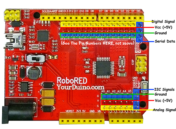
All regular Arduinos have the same overall size and the same long black connector strips across the top and bottom edges. These are female sockets that pins can plug into. YourDuino has added two sets of 3-pin connectors to make it easy for you to connect things. Let's look at the details. First, here is the top connector:
The Yellow Sockets at the very top (Places you can connect wires and devices to) are numbered 0 to 13 from right to left. These are the DIGITAL INPUT/OUTPUT connections. You can push wires or the pins on the end of wires into those "Black Holes" and connect them to many different devices. That's the traditional Arduino way. But it's easier to use the RoboRED connector pins.
We'll be looking at many of the different INPUT DEVICES and OUTPUT DEVICES you can connect to Arduino.

3-pin YourDuino Connectors:
NOTE: If you have a regular Arduino/YourDuino you can plug a [/SensorShield Sensor Shield] on top of it and have the same type of connectors.
YourDuino RoboRED and Robo1 add two sets of connectors to the usual Arduino arrangement. On the RoboRED the DIGITAL Input/Output connector shown above has 3 rows of pins (Yellow, Red and Blue). Look at the labels on the left from top to bottom:
NOTE: See the RoboRED diagrams and information HERE: Notice the labels G, V and S next to the connector rows: G (Ground), V (Voltage) and S (Signal).
S (Signal) Is the Yellow row in this photo. (Some YourDuinos have all black connectors, however) This is the functional connection to whatever devices you use. These pins are connected to the black strip sockets above that have the same numbers.
+ (+5V RAIL) is the Red row
- (GND RAIL) is the Black row.
This arrangement lets you connect devices to YourDuino with a 3-pin cable that provides +5V and GND as well as the SIGNAL connection.
Example: Look at the Servomotor included in your kit. It is like those used in Radio Controlled models. It has a 3-pin plug with black-red-white wires (or brown-red-yellow) that can plug directly on the 3 pin connectors on the YourDuino in a vertical direction, and connect to GND, +5V and SIGNAL. Soon we'll plug your Servo in and try it out.
ANALOG Input Connector:

The row of yellow sockets on the photo above is the other part of the standard Arduino connectors. It includes 6 ANALOG INPUT pins, labelled "A0A1,A2,A3,A4,A5" which means Analog Inputs 0 through 5. Analog inputs can be used to measure voltages, not just see HIGH=1 or LOW=0 like Digital Inputs. We'll use them in a while to measure things.
On the Yourduino Analog Input connector there are 3 rows from Top to Bottom in the opposite order of those at the top. These are:
- (GND RAIL) is the Blue row.
+ (+5V RAIL) is the Red row
S (Signal) Is the Yellow row in this photo. (Some YourDuinos have all black connectors, however)
More about ANALOG INPUTS and other uses of these pins later.
I2C "I squared C" Connector: (WikiPedia)
At the right of the photo above there is a blue 4-pin connector oriented vertically. This makes it easy to connect I2C protocol devices such as LCD displays. These devices use Ground, Vcc, and the two data signals SDA and SCL. The LCD Page HERE shows how this connection matches up.
LESSON 4: COMPONENTS: LEARNING ABOUT INPUT DEVICES
YourDuino BASIC STARTER SET CONTENTS:
Now, let's get practical and look at the contents of the Starter Kit. Take each component out and get a good look at it, especially its connections. Refer to the Component Identification document for details. We'll use the following chart to see how things work together. On the left are the

 Sensor Inputs. On the right are the Action Outputs.

We have provided [/YourDuinoStarterSoftwareSketches short Software Sketches (LINK)] on the ArduinoInfo.Info site which you can cut and paste into a blank page in the Arduino IDE to test with and learn about each of the different Kit components.
Making Connections:
Let's look at Arduino in more electrical detail. The diagram below shows how we will connect things to Arduino and what it means if something is connected or switched to HIGH=5V or LOW=0.0V :
DIGITAL "SIGNALS":
When a PIN (or wire or connection) changes from 0 to 1, or 1 to 0, we say it is a SIGNAL. Kind of like someone raising up a flag or lowering it.

 DIGITAL OUTPUT "SIGNALS": An LED or Buzzer connected to an Arduino OUTPUT can "signal" you that something has happened.

 DIGITAL INPUT SIGNALS: If you push a button that changes an INPUT, you "signal" Arduino that something should be done.
BITS !
Oh, um.. what's a BIT anyway? It is a Binary InTeger which is a number which has only two possible values: 0 and 1. Each YourDuino Input or Output PIN is one BIT inside Yourduino. (A GROUP of 8 BITS is called a BYTE. Bet you knew that!).
DIAGRAMS:
Often an actual circuit (like the Arduino and Breadboard hookup) gets to be a confusing bunch of wires and components going in all directions. And Printed Circuit Boards like the Arduino UNO are not obvious at all. To keep our heads together, we draw  Circuit Diagrams  (like the one above) to show what we're trying to do. Notice the  Symbols  used in the diagram for things like:  SWITCH, RESISTOR, LED.  And there are  Labels  on connections, like  GND, INPUT, OUTPUT  etc. Note the parallel lines of  +5V HIGH  on the diagram, and  GND - LOW  on the diagram which are labelled "RAILS". These are much like Railroad RAILS across the top and bottom. Almost everything that happens on Arduino is between the +5V HIGH RAIL and the GND-LOW (0.0V) RAIL.
 (If you want to see the diagram for the Arduino UNO, it's HERE)

Digital Input Examples:
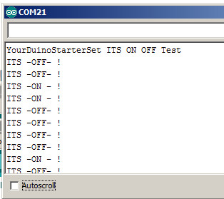
NOTE: Most of the example software Sketches send messages to the "Serial Monitor" that is part of the IDE, like the example below on the right. See How To Use The Serial Monitor HERE:

  The Arduino Digital pins are either ON or OFF. Here's our Terminology:

  ON = 1 = HIGH = +5 Volts

  OFF = 0 = LOW = 0.0v = Ground

  Notice on the photo (R) that +5V is connected to the RED colored strip, and GROUND is connected to the BLUE colored strip.

  Let's check some of these out:
- Pushbutton Switches: We will connect these to a Digital Input and use them with a "Pulldown Resistor" (shown above) that will keep the input pulled LOW=0=OFF until you push the button and the switch pulls the input HIGH=1=ON.
- PhotoResistors: These change their resistance to be low when light hits them. We will connect them just like the pushbutton and when enough light hits them they will pull the input H
 IGH.
IGH.

Hook up a pushbutton switch and 10K pulldown
resistor like the photo above right. Plug the switch so two close-together pins are down. The connections are:
- Wire from +5V on YourDuino to + HIGH Rail (Red)
- Wire from GND on YourDuino to - LOW Rail (Blue)
- Wire from High Rail to Switch (left pin)
- 10K resistor from Switch (right pin) to LOW Rail
- Wire from Switch (right pin) to YourDuino Pin 3
EXAMPLE SOFTWARE SKETCH FOR THIS SECTION: [/YourDuinoStarter_ItsOnOff YourDuinoStarter_ItsOnOff]
 Upload and run this sketch. Open the Serial Monitor. Push the button. The LED 13 on the YourDuino should light, and the Serial Monitor window should look like this (right): THEN replace the switch with a PhotoResistor as shown on the right. Make it quite dark and the LED should go off. More light and the LED will light. Light makes the PhotoResistor have a low resistance.
Read through the sketch to understand how it works and how you would use pushbuttons in the future. There's another Pushbutton example that controls 2 LEDs HERE:
YourDuinoStarter-ButtonInput
LESSON 5: COMPONENTS ANALOG INPUTS

Analog Input Examples:
EXAMPLE SOFTWARE SKETCH FOR THIS SECTION: [/YourDuinoStarter_AnalogValue YourDuinoStarter-AnalogValue]
With Digital Inputs, whatever won the "pullup-pulldown wars" decided if it was 1 or 0. With Analog Inputs, Arduino can see all the VALUES in between HIGH and LOW and make decisions based on those values. An Analog input can sense the Value of things like light levels, battery voltage, or potentiometer position. We'll use the next 2 parts to show how this can work.
- Potentiometer: Look Closely Now at the Potentiometer in the Kit (right). It has 3 terminals that will be connected to: (+5V HIGH) (Gnd LOW) and "Wiper" that will be connected to the Analog Input. When you turn the pot you can move to any voltage in between +5V and Gnd=0. Connect a Pot (Potentiometer) . [PHOTO]EXAMPLE SOFTWARE SKETCH FOR THIS SECTION:
[/YourDuinoStarter_AnalogValue YourDuinoStarter-AnalogValue] The "Pot" acts as a Voltage Divider . Turn it clockwise towards the Top=HIGH=5V or Bottom=LOW=0v and see the values change on the Serial Monitor. - PhotoResistor: We'll use this same component and pulldown resistor, as in the Digital Input example above, but connect it to an Analog Input so we can see all the values as the light level changes.EXAMPLE SOFTWARE SKETCH FOR THIS SECTION:
[/YourDuinoStarter_2AnalogValues YourDuinoStarter-2_AnalogValues]
Read the Sketch to see how things should be connected, and see the photo below right.
Voltage Dividers:

Now let's figure out this Voltage Divider stuff. Look at the diagram on the right. A Voltage Divider has 2 resistors connected in Series, connected to a source of (V)oltage and a (G)round or common point. The connection in the middle between the two resistors is the (S)ignal Output, and is some fraction of the Input Voltage. So we can connect a pot used as a Voltage Divider into the breadboard and connect it with wires.. As we move the pot, the output voltage going to Yourduino varies from 0 to 5 Volts and all the values in between. The way Arduino works gives values from 0 to 1023. If we have a photoresistor connected in series with a resistor, we have a voltage divider that changes with the light intensity, giving us a varying voltage.
What if you want to measure voltages that are more than 5 volts? You use a Voltage Divider to reduce the voltage. If you make a 3 to 1 ratio voltage divider (say, 20K for the top section and 10K for the bottom), then you can read voltages from 0 to 15 volts. Good for automotive batteries. You could to this by putting two of your 10K resistors in series for the top resistor.
LESSON 6: MAKING DECISIONS & CREATING WORKING SYSTEMS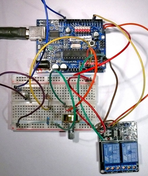

Now we have two Values: Pot position and Light Level. Now we can make comparisons like < (less than) or > (greater that) etc. and make decisions. Let's make an Adjustable Light Level Sensor which controls when a light comes on as it gets dark. It would this work like this:
- READ SENSORS
- Read Potentiometer value
- Read Photoresistor value
- MAKE DECISIONS
- Is Photoresistor value < (less than) Potentiometer value? (Darker)
- TAKE ACTIONS
- Turn Lights on
EXAMPLE SOFTWARE SKETCH FOR THIS SECTION: [/YourDuinoStarter_LightingControl YourDuinoStarter-LightingControl]
Read the comments in the software to understand the details of how this works. See the photo on the right which shows several of our examples combined to make a working Lighting Control system. It includes:
- INPUTS:
- Potentiometer
- PhotoSensor
- OUTPUTS
- LED
- Relay
If you use some longer wires to extend the Photosensor to see outdoor light and connect the Relay Board and have it control the power to your light, you have a practical working system. All these parts are in the Starter Set.
Using Relays:
Digital Outputs are only ON or OFF. We have shown examples of LEDs and the Buzzer, but sometimes you want to turn on or off higher-power devices like room lights, heaters, pumps, motors etc. The Kit includes a 2-channel RELAY board. A relay is a switch that is thrown by an electromagnet, and the switch can handle quite a bit of power. Let's look at some details:

  On the left you see the end of the board with pins to connect to Arduino. We show it connected in the previous photo. On the right you see the relay output connections that you'd use to switch something like 12V or 240V lights, small motors etc. The relay is rated at 10 amps up to 250 VAC or 30 VDC.


How Relay Contacts Work:
Look at the photo of the relay above. Notice the two sets of 3 screw-type terminals. They are given these labels and arranged this way:
|
|
| RelayContacts1-450.jpg |

- NO: Normally Open
- COM: Common Connection
- NC: Normally Closed
Look at the diagram on the right. This shows the switch that is inside the relay. This switch is "thrown" by the electromagnet inside. The diagram shows that COM is connected to the Normally Closed contact. That's the case when the relay is off. When the relay is turned on the electromagnet flips the switch up and COM is then connected to Normally Open. So, if we want a lamp to be on when the relay is on, we connect our circuit from COM to NO.
LESSON 7: ANALOG OUTPUTS: DIMMING LIGHTS & MAKING SOUNDS
Analog Output Examples:
Make an LED Dimmer:
Earlier, you blinked an LED so fast it seemed constant. And by changing the % of time it was on, you could dim it. Arduino has a built-in capability (PWM = PulseWidthModulation) on those upper 6 pins that the Yourduino brings out to 3-pin connectors.
 EXAMPLE SOFTWARE SKETCH FOR THIS SECTION: Y'''ourDuinoStarter_LED_PWM_Dimmer

  See the photo on that page and read the detailed comments in the software to understand how this works and what you can use it for.
  How does this work? Like this:
- READ SENSORS (Read Potentiometer value)
- MAKE DECISIONS (Map 0 to 1023 Pot value to 0 to 255 PWM dimmer value)
- TAKE ACTIONS (Change the dimmer value)
Make a multi-color dimmer with the RGB LED:
The Software Example page will show you how to connect the RGB three-color LED and make thousands of different colors. You need to connect the RBG LED's 3 sections with 3 220 ohm current-limiting resistors.

 EXAMPLE SOFTWARE SKETCH FOR THIS SECTION:
 [/YourDuinoStarter_RGB-LED-Fade  YourDuinoStarter-RGB-LED-Fade]. This looks best when the LED light hits a diffused object like a white ping-pong ball or small plastic bottle from inside.
Make a multi-sound Beeper: This component doesn't make sound by itself like the Buzzer. You use the Tone command to decide what sounds it will make. Connect your Beeper to Yourduino pin 10 and GND.
EXAMPLE SOFTWARE SKETCH FOR THIS SECTION: [/YourDuinoStarter_BeeperTone YourDuinoStarter_BeeperTone]
(which will play you a little tune...)
Read the comments in the software and try some changes.
(SideBar: Using the always-available Arduino reference information)
LESSON 8: SIGNAL: TALKING TO MORE COMPLEX DEVICES
Signal Examples:
Many complex and useful devices do much more than turn ON or OFF or DIM. They communicate with Arduino by sending and/or receiving a series of 1's and 0's that convey information (such as temperature values) according to some protocol. The software to do this is more complex and we will usually use "libraries" of software that the Arduino team or other people have written for us. When we figure out how to do something cool, we may put our code in a Library and share it with others. See more about Libraries andhow to install them so you can use them HERE:
- Servomotor(A Signal Output): Standard servos like the one in the Starter Kit are controlled by ON-OFF signal pulses sent to them. They rotate their output shaft to a position you command them to go to. You can connect your servo directly to a 3-pin connector on the YourDuino. NOTE: The Library software to control servos is part of the regular Arduino IDE; you do not need to download it.
- SERVO SOFTWARE SKETCH 1:YourDuinoStarter-ServoSweep Connect your servo to Pin 9 on the YourDuino 3-pin connector. Read the comments in the software!
- SERVO SOFTWARE SKETCH 2:
YourDuinoStarter_ServoPotPosition With your Pot connected to Analog Pin 0 (First Analog pin) this example makes the servo follow your pot position.
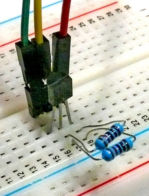 Temperature Sensor(A Signal Input): The DS18B20 temperature sensor in the Kit is an example of the low-cost but complex and accurate sensors that are available. To connect this sensor, see the photo and the details in the software comments.
- The DS18B20 connects with 3 wires: (Gnd) (Signal) (+5v)The sensor is the small device with 3 pins in the center of the photo.
- This sensor needs a "pullup resistor" of about 5K ohms from +5V to Signal pin. We show two of our 10K resistors connected in parallel to make: 5K
- You also need to find, download and install two libraries that do not come with Arduino itself. You will want to learn how to do this to take advantage of the dozens of very useful libraries of software that other Arduino users have shared online. See more about Libraries andhow to install them so you can use them (LINK):
- EXAMPLE SOFTWARE SKETCH FOR THIS SECTION: YourDuinoStarter_TemperatureSensor
- The software has links to get the libraries you need.

LESSON 9: THE ENGINEERING SET DEVICES
These are the 4 devices that are provided in the Engineering Starter Set in addition to those in the Basic set (above):
- 1 - Ultrasonic Distance Sensor [Digital Signal Input]
- 1 - Mini Digital Voltmeter [Visual Display]
- 1 - Small Stepper Motor with driver board [Digital Signal Output]
- 1 - 2.4GHz Radio Data Transceiver board [Digital 2-way Communications]
The software Library you will use for the Stepper Motor is a part of the regular Arduino IDE. But you will need to download libraries for both the Ultrasonic Distance Sensor and the radio transceiver.
See more about Libraries andhow to install them so you can use them (LINK):
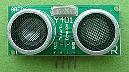 ULTRASONIC DISTANCE SENSOR:

We have an extensive page on this device. Please go there and return for the other devices. See it here (click):
STEPPER MOTOR WITH DRIVER BOARD:

We also have an extensive page on this device. Please go there and return for the other devices. See it here (click):
2.4GHz RADIO DATA TRANSCEIVER BOARD: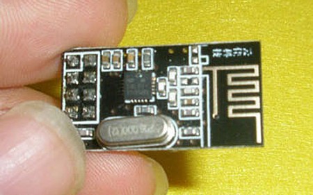

We have a detailed page for this Transceiver. See it here (click):
Mini Digital Voltmeter:
external image thumb_247_RedMeter.jpgThis is not an incredibly accurate meter, with resolution of 0.1 V, but it's an inexpensive way to quickly see the battery voltage on your Robot or RaceCar or your Motor Vehicle battery. It so easy to use: Just 2 wires go to the voltage to be displayed.
- Mounting Hole size: 45.5mm * 26.5mm
- Dimensions: 48mm * 29mm * 21mm
- Range: DC4.0-30V
- Display: three 0.56 LED display
- Refresh rate: about 500ms
- Measurement accuracy: 1% (+ / - 1 count)
- Supply voltage: DC4.0-30V (Same as measured voltage)
Connections:
Ground / Common: Black
+ 4.0 to 30 VDC Power: Red
Conclusion:
Now you have the building blocks and concepts to make many different devices with an Arduino. Look back at  [/YourDuinoStarter#ArchDiag The Diagram we looked at in the beginning]. (Link. Use Back to get Back)
  Hey! You've used all those Input and Output devices and read the Software Sketches that made them work. Now, could you pick some sensor and Read Sensor Inputs, Make some Decisions in software, and Take Actions to make something like one of these??
- Temperature control of a chicken coop with both heat lamps and ventilation fan. [Temperature sensor and 2-channel relay]
- A flickering camp fire made with red and yellow LEDs
- A 6 inch diameter "Dial Thermometer" with a moving pointer showing your living room temperature. [Temperature sensor, Servo]
- ?? What are your ideas ??
The ARDUINO COMMUNITY:
Almost the best thing about Arduino is the community of helpful people around the World who communicate on the Net. Here are some good starting links:
- What People are doing with Arduino
- The official Arduino Discussion Forum
- Project Guidance for Arduino
Where might you go from here?? :
Soon you may want to work on more complex projects. You will use more software libraries, get and use other sensors and actuators, and maybe start communicating from Arduino to the Web. You might even send yourself an SMS.

  Other articles from YourDuino will also cover power: power for Arduino from regular outlets, power from batteries, power for devices that need more than the USB connection can provide, and controlling high power devices from Arduino.

  We'd also like to hear your suggestions. Happy Building!

  Please email comments, critiques, suggestions and questions to:

 terry@yourduino.com
LECCIÓN 8: SEÑAL: EL HABLAR CON DISPOSITIVOS DE COMPLEJOS MÁS
Ejemplos de señales:Muchos dispositivos complejos y útiles hacen mucho más que encender o apagar o DIM. Ellos comunicarse con Arduino mediante el envío y / o recepción de una serie de 1 y 0 que transmiten información (tales como valores de temperatura) de acuerdo con algún protocolo. El software para hacer esto es más complejo y por lo general vamos a utilizar "bibliotecas" de software que el equipo de Arduino u otras personas han escrito para nosotros. Cuando sepamos cómo hacer algo fresco, podemos poner nuestro código en una biblioteca y compartirlo con los demás. Ver más sobre Bibliotecas y [[arduino-info / Arduino-Bibliotecas | cómo instalarlos para que pueda utilizar ellos AQUÍ:]]
- Servomotor (A Señal de salida): servos estándar como el que en el Starter Kit son controladas por impulsos de señal ON-OFF que se les envió. Alternan su eje de salida a una posición que les mandas ir. Puede conectar el servo directamente a un conector de 3 pines en la YourDuino. NOTA: El programa de Biblioteca para controlar servos es parte de la habitual Arduino IDE; no es necesario que lo descargue.
- SERVO SOFTWARE SKETCH 1: [[arduino-info / YourDuinoStarter_ServoSweep | YourDuinoStarter-ServoSweep]] Conecte el servo al pin 9 del YourDuino conector de 3 pines. Leer los comentarios en el software! </ Span>
- SERVO SOFTWARE SKETCH 2:
[[Arduino-info / YourDuinoStarter_ServoPotPosition | YourDuinoStarter_ServoPotPosition]] Con su Pot conectado a analógica Pin 0 (Primera pin analógico) este ejemplo hace que el servo a seguir su posición olla.
- Ancho [[image:DS18B20-BB-CU-500.jpg = altura "250" = "398" align = "right"]] Sensor de temperatura (A Señal de entrada): La temperatura DS18B20 sensor en el kit es un ejemplo de la de bajo costo pero los sensores complejas y precisas que están disponibles. Para conectar este sensor, ver la foto y los detalles en los comentarios de software.
- El DS18B20 conecta con 3 cables: (GND) (señal) </ span> (+ 5v) El sensor es el pequeño dispositivo con 3 pines en el centro de la foto.
- Este sensor necesita una "resistencia de pull-up" de unos 5K ohmios de + 5V a la señal de pata. Mostramos dos de nuestras resistencias 10K conectados en paralelo para hacer: 5K
- También es necesario para encontrar, descargar e instalar dos bibliotecas que no vienen con sí Arduino. Usted tendrá que aprender cómo hacer esto para tomar ventaja de las decenas de bibliotecas muy útiles de software que otros usuarios de Arduino han compartido en línea. Ver más sobre Bibliotecas y [[arduino-info / Arduino-Bibliotecas | cómo instalarlos para que pueda utilizar ellos (LINK):]] </ span>
- Ejemplo DIBUJO DE SOFTWARE PARA ESTA SECCIÓN: [[arduino-info / YourDuinoStarter_TemperatureSensor | YourDuinoStarter_TemperatureSensor]] </ span>
- El software cuenta con enlaces para obtener las bibliotecas que necesita.
Lección 9: LA INGENIERÍA SET DISPOSITIVOS
Estos son los 4 dispositivos que se proporcionan en la Ingeniería Starter Set además de las que en el conjunto básico (arriba):
- 1 - Ultrasonic Sensor de distancia [de señal digital de entrada]
- 1 - Mini voltímetro digital [Visual Display]
- 1 - Pequeño motor paso a paso con la tarjeta de conductor [de señal digital de salida]
- 1 - tablero de 2,4 GHz de datos de radio transmisor-receptor [Digital de 2 vías comunicaciones]
La Biblioteca de software que va a utilizar para el motor paso a paso es una parte de la habitual Arduino IDE. Pero usted tendrá que descargar las bibliotecas, tanto para el sensor de la distancia ultrasónico y el transceptor de radio.
Ver más sobre Bibliotecas y [[arduino-info / Arduino-Bibliotecas | cómo instalarlos para que pueda utilizar ellos (LINK):]]
[[Imagen: SRF06-450.jpg width = "354" height = "180" align = "right"]] ULTRASONIDOS DISTANCIA SENSOR:
Contamos con una extensa página en este dispositivo. Por favor, vaya allí y volver por el resto de dispositivos. [[Arduino-info / UltraSonicDistance | Ver aquí (click):]]
MOTOR DE PASOS CON LA TARJETA DRIVER:
[[Imagen: arduino-info / StepperWithDriver.jpg width = "209" align = "right"]]
También tenemos una extensa página en este dispositivo. Por favor, vaya allí y volver por el resto de dispositivos. [[Arduino-info / SmallSteppers | Vea aquí (click):]] </ span>
2.4GHz RADIO TRANSCEPTOR JUNTA DE DATOS: [[imagen: nRF24L01-3.jpg width = "270" height = "167" align = "right"]]
Tenemos una página detallada de este transceptor. [[Arduino-info / Nrf24L01-2.4GHz-HowTo | Vea aquí (click):]]
[Tipo de clave [media = "costumbre" = "24010494"]] === Mini voltímetro digital: ===
[[Imagen: http: //yourduino.com/sunshop2/images/products/thumb_247_RedMeter.jpg align = "right"]] Esto no es un metro increíblemente precisa, con una resolución de 0,1 V, pero es una manera barata de ver rápidamente el voltaje de la batería del robot o auto de carreras o de la batería del vehículo de motor. Es tan fácil de usar: sólo 2 cables van a la tensión que se mostrará.
- Montaje Tamaño del agujero: 45.5mm * 26.5mm
- Dimensiones: 48mm * 29mm * 21mm
- Rango: DC4.0-30V
- Pantalla: tres visualización 0,56 LED
- Frecuencia de actualización: cerca de 500 ms
- Precisión de la medición: 1% (+ / - 1 cargo)
- Tensión de alimentación: DC4.0-30V (Igual que la tensión medida)
Conexiones:
Planta / Común: Negro
+ 4,0 a 30 VCC Potencia: Rojo
Conclusión:
Ahora usted tiene los bloques y conceptos de construcción para hacer muchos dispositivos diferentes con un Arduino. Mirar hacia atrás en  [/YourDuinoStarter# ArchDiag   El Diagrama vimos al principio] </ span>. (Link. Utilice volver atrás para regresar)
  Hey! Ha utilizado todos los dispositivos de entrada y salida y leer los Bocetos de software que hacen que funcionen. Ahora, ¿podrías recoger algunas sensor y Leer entradas de sensor, tomar algunas decisiones en el software, y tomar medidas para hacer algo como uno de ellos ??
- Control de la temperatura de un gallinero con las dos lámparas de calor y ventilador. [Sensor de temperatura y el relé de 2 canales]
- Un fuego del campo parpadeante hecha con LEDs de color rojo y amarillo
- Un diámetro de 6 pulgadas "Dial Termómetro" con un puntero en movimiento que muestra la temperatura de su sala de estar. [Sensor de temperatura, Servo]
- ?? ¿Cuáles son sus ideas ??
El ARDUINO COMUNIDAD:
Casi lo mejor de Arduino es la comunidad de gente amable de todo el mundo que se comunican en la red. Aquí hay algunos buenos enlaces de partida:
- What La gente está haciendo con Arduino
- The Arduino oficial Foro de Discusión
- [Orientación para Arduino]
¿Dónde podría ir desde aquí ?? :
Pronto es posible que desee trabajar en proyectos más complejos. Que va a utilizar más bibliotecas de software, obtener y utilizar otros sensores y actuadores, y tal vez empezar a comunicarse de Arduino a la Web. Es posible que incluso usted mismo enviar un SMS.

  Otros artículos de YourDuino cubrirán también el poder: el poder para Arduino en puntos de venta habituales, la energía de las baterías, la energía para los dispositivos que necesitan algo más que la conexión USB puede proporcionar, y el control de los dispositivos de alta potencia de Arduino.

  También nos gustaría escuchar sus sugerencias. Feliz Building!

  Por favor enviar comentarios, críticas, sugerencias y preguntas a:

 terry@yourduino.com