YourDuinoStarterSet-MAKE-Version
YourDuino.com Starter Set (MAKE Version)
This page has specific how-to information for the version of the Starter Set as seen in MAKE Magazine January 2013. You can use it with any similar components. Please email comments, critiques, suggestions and questions to: terry@yourduino.com

 This Starter Set comes with a heavy-duty ABS plastic box, seen here:


  Usually this Starter Set is delivered as the box shown here and a small box containing the YourDuino Microcomputer board and all other parts. A page is included picturing and describing all the components. You should use that to unpack the components and become familiar with each one before putting them in the box as shown above.

  You're probably here because you're interesting in MAKING things with Arduino. The first questions:

- What can you do with a MicroComputer like Arduino?
- How do you get started?
What Can You Do with Arduino?? See this link (To be Updated!)
To get started, we think you need 3 things:
- Clear Information
- Practical, Low-Cost hardware to learn with
- Detailed How-To DO IT.
This document will be available online here on the ArduinoInfo WIKI (http://ArduinoInfo.Info) , and soon as a printable PDF.
Making things with Electronics and MicroComputers is different than Woodworking or Metalworking.
There are couple of little problems: Uh Oh!
- Electricity is INVISIBLE !
- AND, Software is INVISIBLE !
Not to worry! We will show you the ways to make these powerful tools Visible so you can use them.
LET's GET STARTED:
If you already have the Arduino IDE Software installed [/YourDuinoStarterSet-MAKE-Version#StartAhead You can Skip Ahead HERE:]
Download and Install the free Arduino IDE Software
Using the Arduino "IDE" software looks virtually the same on Windows, MAC or Linux, but the Installation procedures are different. Below, you can pick which one you need.
Oh, "What's this IDE thing all about anyway" ?? The Arduino Integrated Development Environment
(WikiPedia) is the one place you can do almost everything about Arduinos and Arduino software Development.
Now, go to the official Arduino site to download and install the software for your operating system:
- [/ArduinoInstall-MAC MAC Installation]
- [/ArduinoInstall-WIN WINDOWS Installation]
- Linux Installation
After Installation, or if your board is already installed, continue here:
 CHECK OUT THE YourDuinoRobo1:
On the right, let's look at some of the features of the Robo1 board included in your Starter Set. At the lower left is the PWR LED which should light up whenever the board is plugged into a USB connection, or has power from an external power supply.
  At the upper left there are two green LEDs which will blink when a software sketch is being downloaded to the board, or other data is being transferred over USB.
  At the top is a red LED which is internally connected to pin 13 through a current-limiting resistor. It should blink after you load the example BLINK software sketch. The colored 3-pin connectors make it easy to connect many input and output devices. Details later.
(FOR ALL OF US, NOW: MAC, WINDOWS, LINUX):
RUN THE ARDUINO "IDE" SOFTWARE:
OK, so you've got your YourDuino/Arduino plugged in and running. The POWER"ON" LED is on, right? And the "13" LED is (probably) blinking.
Soon we'll start connecting the things in the Starter Set, but first we'll use that built-in Pin 13 LED to get started.
IT'S SOFTWARE TIME:
Let's take a little while to get used to writing Arduino Software, then we'll come back and start connecting your Starter kit parts and making more interesting things. We will give you software examples for each of the devices in the Starter Set.

  On your desktop you should now have the Arduino ICON like this:
|
|
| external image Arduino-Icon1-68.jpg |

 Click on it, if you haven't already, and you should see the "Arduino IDE Window" pop up like this:

  You'll use this IDE (Integrated Development Environment) to make Software VISIBLE! Here you will develop your own software to make Arduino into what you want it to be.

SKETCHES:
The visible text of an Arduino software program is called a SKETCH. But the Sketch becomes alive when you upload it to your Arduino. Let's walk through looking at a Sketch and Verifying it and Uploading it:

 Click on FILE and then move your mouse (slowly.. It's Fussy!) over EXAMPLES and BASICS and BLINK
  so it looks like this (On the right):
 And CLICK. There are lots of examples that come with the free Arduino software system, and we will look at some of them later, as well as make our own very soon.

  A new IDE window should pop up and look like this:

  Wow.. A bunch of new stuff.

  Let's slow down and "Watch Closely Now"!

  Notice that a lot of the text is GRAY. All of that is just "Comments" for you to read to help understand the Sketch. When you write software, you should also use "Comments" to explain to others what you are doing. (Arduino itself totally ignores these comments).

  Now, let's go through Editing software, Verifying it, and Uploading it to see Arduino DO it. We'll use the BLINK example for now, but in a while you'll start with a totally blank page and write your own programs.


STRUCTURE OF ARDUINO SOFTWARE:
Every Arduino Software Sketch has two main parts:
- SETUP - Runs Once at the beginning
- LOOP - Runs over and over again, forever
You will read a LOT of program "Code" that other people wrote, in the future. You HAVE to "Watch Closely Now" and really see the details. Read the example through carefully, a couple of times. Note the colored special words that are Instructions. These are unique words that tell Arduino what to do. They have to be spelled perfectly!
What SETUP does: Instructs Arduino about things that need to be done once. Remember that Arduino Digital Pins can be either INPUT or OUTPUT. You have to tell Arduino when a Pin will be used as an OUTPUT. In this example, there is one line that tells Arduino that Pin 13 must be an OUTPUT.
external image Arduino-IDA-Pinmode1.jpg
Note the COLOR of the lettering. The Arduino IDE changes the color of words as it recognizes them as special instructions. Let's mess with them:
pinMode: Note that when Instructions are two words run together, like pinMode, the beginning of the SECOND word is Capitalized. Mess with it: Change the Capital "M" to "m". Note the color changes to black. Hmmm. Click the VERIFY ![]() button.
button.
You will get an ERROR message: ![]()
Fussy, Fussy, Fussy! Yep, every letter has to be correct and also correct upper or lower case.
Change it back. Check the color. Click Verify again. OK??
What LOOP does: Loop contains all the active parts of your Sketch that continue to run after SETUP is finished. It will run over and over again, forever, or until you stop it or power down.
What does VERIFY do??![]()
A LOT! More details later, but Verify is a program in your main computer that goes through every Instruction in your Sketch (Ignoring "Comments") and checks it against the list of valid Instructions, and checks that the structure and sequence of the statements in the Sketch are correct. Fussy, Fussy! If that's OK, then it "compiles" or "translates" the sketch into the actual machine code that Arduino actually runs on. It saves that 'ready-to-run' code for you to Upload to Arduino and run. Other systems would call this process "Make" or "Compile".
What does UPLOAD do??![]()
First, Upload runs Verify to check and compile your program. Then it communicates to your Arduino over the USB connection, resets the Arduino chip, and talks to software already on Arduino (called the BOOTLOADER(W)) to load your new program into the Arduino's memory. Then it restarts Arduino and your program runs it's SETUP section and then repeats the LOOP section.
[NOTE: The (W) Means this is a Wikipedia link.]
Start Making Changes:
Ok, let's make a few changes to the sample BLINK program:

The LOOP section of your program does all the instructions in the section, and then "loops" back to the top and starts it again, over and over.
NOTE: the "Brackets" { and }
Notice that the beginning and end of the section is "inside brackets". You will see many sections of bigger programs that are grouped by these "brackets".
Now, let's look in detail at the instructions:
Instruction: digitalWrite
This instruction sets an OUTPUT PIN to either HIGH (connects it to +5 V) or LOW (Connects it to GND).
Remember: HIGH = 1 = ON = 5 Volts and LOW = 0 = OFF = 0.0 Volts
So, the first line in LOOP sets PIN 13 to HIGH. This means Pin 13 is connected to +5 Volts, and current flows through the resistor and LED that are already connected to pin 13. The LED lights up.
Instruction: delay
The delay instruction just waits for a period of time. The VALUE used with delay is in Milliseconds (1/1000 second). So delay(1000); waits for 1000/1000 seconds (1 second). We'll change that soon.
NOTE: the ";" (Semi-Colon)
Notice that every instruction is followed by the character " ; " which is like a period that tells the end of the sentence. Run-on sentences will make you stay after school to fix your error messages!
Change the delay so that the LED blinks differently:
Time to mess about and try some things! Maybe we'll break it. Then we'll fix it..
Suggestion: Save your own version of BLINK so you can always go back to the original one. Go to File and Save As and call it something like MyBlink. This will go in your [***TBD] SKETCHBOOK where you'll save your own programs.
Now go change the VALUE in a delay statement to change the way the LED blinks. Think about the the 4 instructions in LOOP. What's happening??
- Turn the LED on. Wait and look at the LED.
- Turn the LED off. Wait and look at the dark.
So, let's change the ON time to be short. Maybe 50 Milliseconds. That's 1/20 of a second. Then try 10 milliseconds. The LED is only on 1/100 of the time. Can you still see it blink? How about 1 millisecond?
Each time you make a change, click Upload![]() which will first Verify and Compile your program and then send it to Arduino. Notice that each time you do this the LEDS that are marked "Tx" (Transmit) and "Rx" (receive) flash as your main computer communicates with your Arduino.
which will first Verify and Compile your program and then send it to Arduino. Notice that each time you do this the LEDS that are marked "Tx" (Transmit) and "Rx" (receive) flash as your main computer communicates with your Arduino.
Try some combinations of ON and OFF times. Like ON 1000 and OFF 50.
Try making both ON and OFF times shorter and shorter. If you make the ON and OFF times short enough your eye will no longer see blinking, because of "Persistence of Vision"(W) which happens when there are more than about 25 blinks per second. So, hmmm.... if you make the LED be ON for 1/50 of a second and OFF for 1/50 of a second that should do it. So try 1000/50= 20 Milliseconds. Put 20 for both the ON and OFF times. What do you see?? How about 10 Milliseconds each? Depending on your personal eye's physiology, at some speed you will not see any more blinks.
All right. You're the Programmer! You can save any of the sketches for use later on. Go to File>Sketchbook and you'll see them.
Next, we'll start hooking up Electronics Parts! And we'll give you example Software Sketches for them.
BREADBOARDS, WIRES, PINS, CABLE and ELECTRONICS COMPONENTS:
Arduino is great but sometimes connecting interesting things to it can be a pain. We tried to make it easier for you. We will use a BREADBOARD (W) for most connections.
The idea here is that wires and electronics parts like LEDs and RESISTORs have wire leads that can be plugged into the BREADBOARD and then easily be removed or changed. The holes in the BREADBOARD go down into little sockets with metal contacts.
Sections of the BREADBOARD have rows or columns that are all connected together, making it easy to have multiple things connected together.
Here's some detail of how the BREADBOARD that we use in this kit is organized:
external image BreadBoard-1.jpg
The Horizontal Rows have 5 holes (abcde) and (fghij) with sockets that are connected together. Any wires or parts that are plugged into this row are connected together.
The Vertical Columns (+Red and -Blue) have the same connection running all the way down. We will use these to connect 5V on our YourDuino board to the +Red and to connect GND on our YourDuino board to -Blue. Then any time we need to connect to GND, we just plug a wire or part into the -Blue column, and any time we need to connect to 5V, we just plug a wire or part into the +Red column.
Now let's look again at the YourDuinoRobo1 board and where we will make connections there. Later we will look at the board in a lot more detail, but for now let's just hook up a few things and make them work.
The first thing we want to do is connect GND on the board to a -Blue column on the breadboard and 5V on the board to a +Red column.
We will orient the breadboard left-to-right so it can sit in front of the YourDuino board so we can easily make many connections and changes.
 So it will look something like this:
We will mainly use the upper +Red row and the bottom -Blue row. Often we think of these parallel lines as "Rails" like railroad rails. The top red rail is the "+5 Volt Rail" and the bottom blue rail is the "Ground Rail". "Voltage Rails" (Wikipedia) is a common terminology in electronics.
How to THINK about Arduino:
We will use this picture to think about how we connect things to Arduino. It shows the +5V and Ground "Rails". (More about Diagrams later). 
What about wires? Locate the "40 pin flat cable" and the "Male-Male Pin Connectors" in your kit.
To start we will connect the "5V Rail" to "5V" on the YourDuino board.
WIRES:
We will use the "40 pin flat cable" in your kit for wires. It looks like this:


  You can easily strip off one or more wires, or strip off a section to use as a cable. The ends of these wires are female connectors that can plug onto the connectors on the Robo1 or a "Sensor Shield". But what about the breadboard?? It needs a wire with a male end to plug into it. The pin strips (Right) are the answer. Your kit has 2 of these with 40 pins each. You can cut or snap off the number of pins you need. For now, snap/cut off about 6 single pins. It's easier to snap off just 1 pin if you grab it with a small pair of pliers of some kind.


Here's the way this works:
|
|
| male pins (left) |

|
|
| female wire ends |

|
|
| 3-pin strip |

|
|
| 3-pin cable end |

You can make any combination of male or female cable ends of different widths.
 Now, let's connect your Breadboard to the YourDuino board:
* TBD: Replace Photo R
Strip off 1 Blue wire and 1 Red wire from your flat cable. Run the Red wire from a +5 pin on the YourDuino to the +Red Rail on the breadboard. Run the Blue wire from a GND pin on the YourDuino to the -Blue Rail on the breadboard. Now it's easy to connect things to the 5V (+Red) Rail or the GND (-Blue) Rail. We show +5 and Gnd connected to the pins on the far right side of the Yourduino board.
 See the close-up photo here, and plug a 220 Ohm (Red-Red-Brown) resistor [TBD: Color Code] and a red LED (Long pin to the left) into the Breadboard as shown. (Use male-male pins where you need a male end to plug into the breadboard or YourDuino).
Now add a wire (Black is shown) from the same vertical strip as the LED to the GND Rail. Connect another wire (Green is shown) to the same vertical strip as the left end of the resistor, and use a pin to plug it into the YourDuino socket labelled 13.
Time to Power Up! Plug the USB cable from your computer into the YourDuino. Its PWR LED should come on. And the pin 13 LED should be blinking in the way you last programmed it. If necessary load the original GOBP (Good Old Blink Program!) and Upload it to YourDuino. Your setup should look like the photo on the right above. AND the LED you just wired up on your Breadboard should blink the same as the 13 LED on YourDuino. NO? Recheck that you have it wired like the photos, and the the LED's longer lead is to the left.
Let's figure out what's really happening here. Unplug the wire from YourDuino pin 13 (keep the pin with it). Now try two things:
- Plug the free end of the wire into the +5V Rail. It should light up.
- Plug the free end of the wire into the GND Rail. It should be off.
Try it a few times, like 1 second to +, 1 second to GND. Now plug it back into YourDuino Pin 13. It should blink again.
What's happening here?? The YourDuino is doing exactly the same thing automatically that you did manually! It is connecting the circuit connected to pin 13 to the +5V Rail and then connecting it to the GND Rail.
Another Digital Output Device: Try connecting the Buzzer (not the Beeper) temporarily in place of the LED. It should make a noise in the same timing as the LED.
That's how "Digital Outputs" work.
OK, you have a good beginning in setting up YourDuino, Programming it, and wiring up external devices.
Now, let's slow down a bit. In our next section, we'll think about what's going on here, which is CIRCUITS.
And what's all this stuff about PINS , BITS , ONES and ZEROS , HIGH and LOW... ? ?
In the next section:
PINS...
BITS...
ONES and ZEROS...
HIGH and LOW...
... YOU'LL KNOW!!
Here's how we will think about Arduino and the three main things that are part of all automatic systems:
[Sensor Inputs | Software Behavior | Action Outputs]
All automatic systems, from a simple thermostat to the Mars Rover have those 3 parts.
Sensor Inputs:
These can be simple like a pushbutton switch or complex like a GPS receiver. There are hundreds of possibilities for sensing things in the Physical World.
Action Outputs:
These can be simple like an LED or complex like the motors and motion control of a Robot.
Software Behavior:
This is where you decide what Sensor Inputs Arduino will look at, what Decisions it will make about its Behavior, and what Action Outputs it will cause to happen. You make this actually work by writing software code statements.
OK, time to stop talking and hook real things up to those INPUTS and OUTPUTS. Look at YourDuino again for a minute. You'll get to know it well:
Take a couple of minutes to look at it closely. If you haven't done much detailed electronics it looks like a jumble. But slow down and look at the different parts.
What's important to us first?? We need to connect stuff, so we'll look at the connectors.
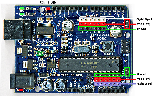
All regular Arduinos have the same overall size and the same long black connector strips across the top and bottom edges. These are female sockets that pins can plug into. YourDuino has added two sets of 3-pin connectors to make it easy for you to connect things. Let's look at the details. First, here is the top connector:
The Sockets (Places you can connect wires and devices to) are numbered 0 to 13 from right to left. These are the DIGITAL INPUT/OUTPUT connections. You can push wires or the pins on the end of wires into those "Black Holes" and connect them to many different devices.
We'll be looking at many of the different INPUT DEVICES and OUTPUT DEVICES you can connect to Arduino.

3-pin YourDuino Connectors:
NOTE: If you have a regular Arduino/YourDuino you can plug a [/SensorShield Sensor Shield] on top of it and have the same type of connectors.
YourDuino adds two sets of connectors to the usual Arduino arrangement. The DIGITAL Input/Output connector shown above has 3 rows of pins (White, Red and Black). Look at the labels on the left:
S (Signal) Is the White row in this photo. (Many YourDuinos have all black connectors, however) This is the functional connection to whatever devices you use. These pins are connected to the sockets above that have the same numbers.
+ (+5V RAIL) is the Red row
- (GND RAIL) is the Black row.
This arrangement is so that you can connect devices to YourDuino with a 3-pin cable that provides +5V and GND as well as the SIGNAL connection. Notice that +5V and Gnd are also easily available on the pins on the far right, not just the one 5V pin on regular Arduinos.
Example: Look at the ServoMotor included in your kit. It is like those used in Radio Controlled models. It has a 3-pin plug with black-red-white wires (or brown-red-yellow) that can plug directly on the 3 pin connectors on the YourDuino in a vertical direction, and connect to GND, +5V and SIGNAL. Soon we'll plug your Servo in and try it out.
DIGITAL Input/Output Connector:
Look closely at the connector above. Notice that it is numbered: 11 10 9 6 5 3 . This means that those YourDuino pins are the ones made available on the 3-pin connectors. Also, all of those pins have the capability for "PWM" which means "Pulse Width Modulation" and can be used to control the amount of power sent to an output device, dim LEDS etc. We'll try that out soon.
ANALOG Input Connector:

This row of black female sockets on the lower right is the other part of the standard Arduino connectors. It includes 6 ANALOG INPUT pins, labelled "0 ANALOG IN 5" which really means Analog Inputs 0 through 5. Analog inputs can be used to measure voltages, not just see HIGH=1 or LOW=0 like Digital Inputs. We'll use them in a while to measure things.
On this Analog Input connector there are 3 rows from Top to Bottom in the opposite order of those at the top. These are:
- (GND RAIL) is the Black row.
+ (+5V RAIL) is the Red row
S (Signal) Is the Purple row in this photo. (Many YourDuinos have all black connectors, however)
More about ANALOG INPUTS and other uses of these pins later.
STARTER SET CONTENTS:
Now, let's get practical and look at the contents of the Starter Kit. If you didn't do this when you unpacked your components, take each component out now and get a good look at it, especially its connections. We'll use the following chart to see how things work together. On the left are the Sensor Inputs. On the right are the Action Outputs.

[We will provide [/YourDuinoStarterSoftwareSketches short Software Sketches] (LINK) on the ArduinoInfo.Info site which you can cut and paste to test with and learn about each of the different Kit components. The first ones are done; others Under Construction]
Making Connections:
Let's look at Arduino in more electrical detail. The diagram below shows how we will connect things to Arduino and what it means if something is connected or switched to HIGH=5V or LOW=0.0V :
DIGITAL "SIGNALS":
When a PIN (or wire or connection) changes from 0 to 1, or 1 to 0, we say it is a SIGNAL. Kind of like someone raising up a flag or lowering it.
DIGITAL OUTPUT "SIGNALS": An LED or Buzzer connected to to an Arduino OUTPUT can "signal" you that something has happened.
DIGITAL INPUT SIGNALS: If you push a button that changes an INPUT, you "signal" Arduino that something should be done.
BITS !
Oh, um.. what's a BIT anyway? It is a Binary InTeger which is a number which has only two possible values: 0 and 1. Each YourDuino Input or Output PIN is one BIT inside Yourduino. (A GROUP of 8 BITS is called a BYTE. Bet you knew that!).
DIAGRAMS:
Often an actual circuit (like the Arduino and Breadboard hookup) gets to be a confusing bunch of wires and components going in all directions. To keep our heads together, we draw Circuit Diagrams (like the one above) to show what we're trying to do. Notice the Symbols used in the diagram for things like: SWITCH, RESISTOR, LED. And there are Labels on connections, like GND, INPUT, OUTPUT, ARDUINO etc. Note the parallel lines of +5V HIGH on the diagram, and GND - LOW on the diagram which are labelled "RAILS". These are much like Railroad RAILS across the top and bottom. Almost everything that happens on Arduino is between the +5V HIGH RAIL and the GND-LOW (0.0V) RAIL.
NOTE: The following section is still somewhat "Under Construction Today". But there are Example Software Sketches for each type of part shown. For now, see the list of them here: [/YourDuinoStarterSoftwareSketches YourDuinoStarter Sketches:]
Digital Input Examples:
The Arduino Digital pins are either ON or OFF. Here's our Terminology:

 ON = 1 = HIGH = +5 Volts

 OFF = 0 = LOW = 0.0v = Ground

 EXAMPLE SOFTWARE SKETCH FOR THIS SECTION: [/YourDuinoStarter_ItsOnOff "IT's ON-OFF"]
- Pushbutton Switches: We will connect these to a Digital Input and use them with a "Pulldown Resistor" (shown above) that will keep the input pulled LOW=0=OFF until you push the button and the switch pulls the input HIGH=1=ON. (Sidebar: The "Serial Monitor")
- PhotoResistors: These change their resistance to be low when light hits them. We will connect them just like the pushbutton and when enough light hits them they will pull the input HIGH. (Breadboard Photo)
Analog Input Examples:
EXAMPLE SOFTWARE SKETCH FOR THIS SECTION: [/YourDuinoStarter_AnalogValue AnalogValue]
With Digital Inputs, whatever won the "pullup-pulldown wars" decided if it was 1 or 0. With Analog Inputs, Arduino can see all the VALUES in between HIGH and LOW and make decisions based on those values. An Analog input can sense the Value of things like light levels, battery voltage, or potentiometer position.
- Potentiometer: Look Closely Now at the Potentiometer in the Kit. (Photo/drawing) It has 3 terminals that will be connected to: (+5V HIGH) (Gnd LOW) and "Wiper" that will be connected to the Analog Input. When you turn the pot you can move to any voltage in between +5V and Gnd=0. Connect a Pot (Potentiometer) and run (Software: AnalogLevel) The "Pot" acts as a Voltage Divider . Turn it clockwise towards the Top=HIGH=5V or Bottom=LOW=0v and see the values change on Serial Monitor.
- PhotoResistor: Now we'll use this same component and pulldown resistor, as in the diagram above, but connect it to an Analog Input so we can see all the values as the light level changes.(See Example Software: 2AnalogValues)
Voltage Dividers: * 2-resistor divider??

Now let's figure out this Voltage Divider stuff. Look at the diagram on the right. A Voltage Divider has 2 resistors connected in Series, connected to a source of (V)oltage and a (G)round or common point. The connection in the middle between the two resistors is the (S)ignal Output, and is some fraction of the Input Voltage. So we can connect a pot used as a Voltage Divider to one of our 3-wire cables that have (-)(+)(S) connections as marked on the YourDuino . As we move the pot, the output voltage going to Yourduino varies from 0 to 5 Volts and all the values in between. The way Arduino works gives values from 0 to 1023. If we have a photoresistor connected in series with a resistor, we have a voltage divider that changes with the light intensity, giving us a varying voltage.
Measuring other voltages:** What if you want to measure voltages that are more than 5 volts? You use a Voltage Divider to reduce the voltage. If you make a 3 to 1 ratio voltage divider (say, 20K for the top section and 10K for the bottom), then you can read voltages from 0 to 15 volts. Good for automotive batteries.
Making Decisions:
Now we have Values so we can make comparisons like < (less than) or > (greater that) etc. and make decisions. Let's make an Adjustable Light Level Sensor which controls when a light comes on as it gets dark. It would this work like this:
- READ SENSORS
- Read Potentiometer value
- Read Photoresistor value
- MAKE DECISIONS
- Is Photoresistor value < (less than) Potentiometer value? (Darker)
- TAKE ACTIONS
- Turn Lights on
(See Example software Here : LightingControl) Read the comments in the software to understand the details of how this works. If you use some longer wires to extend the Photosensor to see outdoor light and connect the Relay Board to the same pin as the LED and have it control the light, you have a practical working system.
Digital Output Examples:
Digital Outputs are only ON or OFF. We have shown examples of LEDs and the Buzzer, but sometimes you want to turn on or off higher-power devices like room lights, heaters, pumps, motors etc. The Kit includes a 2-channel RELAY board. A relay is a switch that is thrown by an electromagnet, and the switch can handle quite a bit of power. Let's look at some details:
  On the left you see the end of the board with pins to connect to Arduino. We'll show it connected later. On the right you see the relay output connections that you'd use to switch something like 12V or 240V lights, small motors etc. The relay is rated at 10 amps up to 250 VAC or 30 VDC.


How Relay Contacts Work:
Look at the photo of the relay above. Notice the two sets of 3 screw-type terminals. They are given these labels and arranged this way:
|
|
| RelayContacts1-450.jpg |

- NO: Normally Open
- COM: Common Connection
- NC: Normally Closed
Look at the diagram on the right. This shows the switch that is inside the relay. This switch is "thrown" by the electromagnet inside. The diagram shows that COM is connected to the Normally Closed contact. That's the case when the relay is off. When the relay is turned on the electromagnet flips the switch up and COM is then connected to Normally Open. So, if we want a lamp to be on when the relay is on, we connect our circuit from COM to NO.
Analog Output Examples:
In Article 1 you blinked an LED so fast it seemed constant. And by changing the % of time it was on, you could dim it. Arduino has a built-in capability (PWM=PulseWidthModulation) on the 6 pins that the Yourduino brings out to 3-pin connectors. Try it: (This Software not done yet!: LED_Dimmer) Read the detailed comments in the software to understand how this works and what you can use it for.
  How would this work? Like this:
- READ SENSORS (Read Potentiometer value)
- MAKE DECISIONS (Adjust 0 to 1023 Pot value to 0 to 255 PWM dimmer value)
- TAKE ACTIONS (Change the dimmer value)
You can also connect the RGB three-color LED and run this to make different colors. You need to connect the RBG LED's 3 sections with 3 220 ohm current-limiting resistors. See [/RGB-LED Red-Green-Blue (RGB) LEDs HERE]
Load and try the[/YourDuinoStarter_RGB-LED-Fade The RGB LED software example here:]. This looks best when the light hits a diffused object like a white ping-pong ball or small plastic bottle from inside.
Beeper: This component doesn't make sound by itself like the Buzzer. You use the Tone command to decide what sounds it will make. Connect your Beeper to Yourduino pin 10 and GND. Try it with [/YourDuinoStarter_BeeperTone the example Software Here: YourDuinoStarter Example: - Beeper_Tone]
Read the comments in the software and try some changes.
(SideBar: Using the always-available Arduino reference information)
Signals:
Many complex and useful devices do much more than turn ON or OFF or DIM. They communicate with Arduino by sending or receiving a series of 1's and 0's that convey information (such as temperature values) according to some protocol. The software to do this is more complex and we will usually use "libraries" of software that the Arduino team or other people have written for us. When we figure out how to do something cool, we may put our code in a Library and share it with others. (Sidebar: Libraries )
- Servomotor: (Signal Output) Standard servos like the one in the Starter Kit are controlled by ON-OFF signal pulses sent to them. You can connect your servo directly to a 3-pin connector on the YourDuino. (Use this Example Software:https://arduinoinfo.mywikis.net/wiki/YourDuinoStarter_ServoSweep) Connect your servo to Pin 9 on the YourDuino 3-pin connector. Read the comments in the software!
- Then try (This Example Software: YourDuinoStarter_ServoPotPosition ) with your Pot connected to Analog Pin 0 (First Analog pin) for an example where the servo follows your pot position.
- Temperature Sensor: (Signal Input) The DS18B20 temperature sensor in the Kit is an example of the low-cost but complex and accurate sensors that are available. To connect this sensor, see the photo and the details in the software comments. You also need to find, download and install two libraries that do not come with Arduino itself. You will want to learn how to do this to take advantage of the dozens of very useful libraries of software that other Arduino users have shared online. See the sidebar "Libraries". (Use This Example Software: YourDuinoStarter_TemperatureSensor
[Graphic: Breadboard connection for Temperature Sensor]
Conclusion:
Now you have the building blocks and concepts to make many different devices with an Arduino. Look back at [***FIG X] . You've used all those Input and Output devices and read the Software Sketches that made them work. Could you pick some sensor and Read Sensor Inputs, make some Decisions in software, and Take Actions to make something like one of these??
- Temperature control of a chicken coop with both heat lamps and ventilation fan. [Temperature sensor and 2-channel relay]
- A flickering camp fire made with red and yellow LEDs
- A 6 inch diameter "Dial Thermometer" with a moving pointer showing your living room temperature. [Temperature sensor, Servo]
- ?? What are your ideas ??
The ARDUINO COMMUNITY:
Almost the best thing about Arduino is the community of helpful people around the World who communicate on the Net. Here are some good starting links:
- What People are doing with Arduino
- The official Arduino Discussion Forum
- Project Guidance for Arduino
Next:
We will be looking at what you need to do more complex projects. You will use more software libraries, get and use other sensors and actuators, and start communicating from Arduino to the Web. You might even send yourself an SMS. We'll also cover power: power for Arduino from regular outlets, power from batteries, power for devices that need more than the USB connection can provide, and controlling high power devices from Arduino. We'd also like to hear your suggestions. Happy Building!

  Please email comments, critiques, suggestions and questions to:

 terry@yourduino.com