Relay-Board-How-To
A RELAY is: A Switch that is "thrown" by an Electromagnet.
Photo above shows 1,2,4 and 8 relays on Opto-Isolated boards.
But first, About Switches:
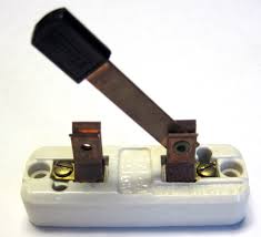
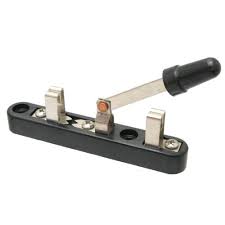
Switches make or break electrical connections. The simple switch on the left makes or breaks one connection.
Switches are labelled as having POLES (how many switches work together) and THROWS (How many different connections they can make).
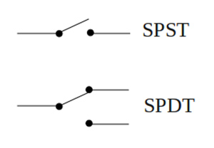
So, the left switch above is a Single Pole - Single Throw switch: The simplest kind.
The switch on the right can be connected two different ways: to the contact on the left OR the contact on the right. So it is a Single Pole - Double Throw switch. Sometimes you will see switches abbreviated: The two examples above would be SPST and SPDT. Often we show switches by their Schematic Diagram [W ]. See the examples on the right.
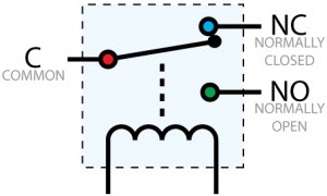 The most common relays used with Arduino are SPDT switches that are Thrown by an electromagnet that can be activated by Arduino or other Microcomputers. The schematic diagram of this type of relay is shown on the right. The two possible contact positions are shown as NC (Normally Closed) and NO (Normally Open). When the relay is activated the electromagnet (shown as a coil of wire) pulls
the C (Common) contact down and it disconnects from the NC contact and connects to the NO contact.
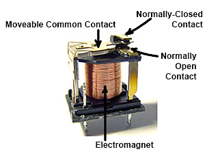
Let's look at what is inside these relays: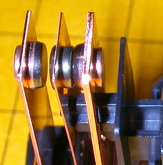
Connecting to a relay board:
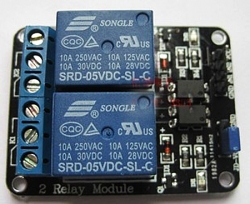
See a typical relay board on the left. Two relays are mounted on a small printed circuit board with added driver transistors, optical isolators and LEDs. The relay contacts are brought out to screw-type terminal strips for easy connections to wires. Each relay has 3 connections. See the closeup on the right.
The connections are labelled "NO", "COM", "NC". Those labels mean:
- NO: Normally Open
- COM: Common Connection
- NC: Normally Closed
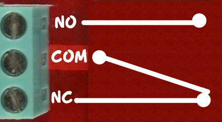
(Sometimes the relay board has a diagram rather than NO-COM-NC labels). Look at the diagram on the right. This shows the switch that is inside the relay. This switch is "thrown" by the electromagnet inside. The diagram shows that COM is connected to the Normally Closed contact. That's the case when the relay is off. When the relay is turned on the electromagnet flips the switch up and COM is then connected to Normally Open. So, if we want a lamp to be on when the relay is on, we connect our circuit from COM to NO.
Multiple Relay Systems:
If you do something a little bit more complex, like controlling an aquarium, a plant growing system, or a home energy management system, you'll need more relays. Let's look more closely at the 4-relay and 8-relay boards shown in the top of page photo. (You can get them here). And you can see their schematic diagrams on the product pages. You can build these circuits yourself if you wish, or prototype things like the examples here.
- More About Relays HERE:
- Good detailed RELAY Information and Tutorial here:
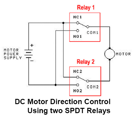
Using two typical SPDT (Single Pole Double Throw) relays to control a DC motor:
DC Motors can be controlled to Run in either direction or stop, with two relays. See the diagram at the right. When both relays are off, both motor terminals are connected to the same point and the motor is stopped. If one relay is activated, one motor terminal is connected to one polarity and it runs in that direction. If the other relay is activated, the motor connected in the opposite polarity. (If Both relays were activated the motor would also stop!).
UNDER CONSTRUCTION BELOW
IMPORTANT NOTE: There is a issue with start-up of Arduino programs that control these relays. All of these 2,4, or 8 relay boards input controls are Active LOW, meaning that setting a pin LOW turns them ON. To assure that no relays activate at Reset or Power-On until you want them to, the initialization sequence in SETUP should be:
- digitalWrite(Relay, HIGH);
- pinMode(Relay, OUTPUT);
This design is intentional, so that it is possible to guarantee that at power-on of a system, or system reset, that no relays activate except when expected under program control. There may be pumps, lights etc. attached and chaos could ensue if this was not controlled definitively for each output port being used.
Then in the main Loop section turn relays On or Off as needed... Following is an example program that properly controls 4 relays on our 4-relay board (Available HERE )
/* YourDuino Example: Relay Control 1.10
  Handles "Relay is active-low" to assure
  no relay activation from reset until
  application is ready.
   terry@yourduino.com */

/*-----( Import needed libraries )-----*/
/*-----( Declare Constants )-----*/
#define RELAY_ON 0
#define RELAY_OFF 1
/*-----( Declare objects )-----*/
/*-----( Declare Variables )-----*/
#define Relay_1  2  // Arduino Digital I/O pin number
#define Relay_2  3
#define Relay_3  4
#define Relay_4  5

void setup()   /****** SETUP: RUNS ONCE ******/
{
//-------( Initialize Pins so relays are inactive at reset)----
  digitalWrite(Relay_1, RELAY_OFF);
  digitalWrite(Relay_2, RELAY_OFF);
  digitalWrite(Relay_3, RELAY_OFF);
  digitalWrite(Relay_4, RELAY_OFF);

//---( THEN set pins as outputs )----
  pinMode(Relay_1, OUTPUT);
  pinMode(Relay_2, OUTPUT);
  pinMode(Relay_3, OUTPUT);
  pinMode(Relay_4, OUTPUT);
  delay(4000); //Check that all relays are inactive at Reset

}//--(end setup )---


void loop()   /****** LOOP: RUNS CONSTANTLY ******/
{
//---( Turn all 4 relays ON in sequence)---
  digitalWrite(Relay_1, RELAY_ON);// set the Relay ON
  delay(1000);              // wait for a second
  digitalWrite(Relay_2, RELAY_ON);// set the Relay ON
  delay(1000);              // wait for a second
  digitalWrite(Relay_3, RELAY_ON);// set the Relay ON
  delay(1000);              // wait for a second
  digitalWrite(Relay_4, RELAY_ON);// set the Relay ON
  delay(4000);              // wait see all relays ON

//---( Turn all 4 relays OFF in sequence)---
  digitalWrite(Relay_1, RELAY_OFF);// set the Relay OFF
  delay(1000);              // wait for a second
  digitalWrite(Relay_2, RELAY_OFF);// set the Relay OFF
  delay(1000);              // wait for a second
  digitalWrite(Relay_3, RELAY_OFF);// set the Relay OFF
  delay(1000);              // wait for a second
  digitalWrite(Relay_4, RELAY_OFF);// set the Relay OFF
  delay(4000);              // wait see all relays OFF


}//--(end main loop )---


//*********( THE END )***********
Below is a 4-relay board and a photo of it being run by the example software Sketch above.
TO BE ADDED
NOTE: This a family of boards with 1,2,4,or 8 relays). (SEE Them HERE))
There are both Optically-isolated versions (recommended for most applications) and non-isolated versions. You would connect Arduino to the connector on the upper left. +5V to VCC, four input pins, and GND.
You can wire the relay outputs to various devices rated at up to 10 Amps.
There are LEDs on the board that show when a relay is active, and a green LED to show that +5V power is applied. Notice how our multicolor flat cable makes this easy to connect! And the YourDuinoRoboRED microcomputer board has those connectors built in.
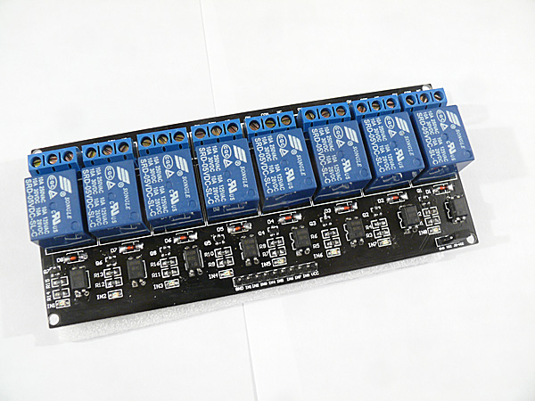
Here is an 8-relay board. (Available HERE) It has an added feature of Optical Isolation. This means that all Arduino really does is turn on an LED inside an IC package, and THAT turns the relay on. So there does not need to be any direct connection between Arduino and the relay driver circuits. This can be an advantage and safety factor when controlling a separate piece of equipment that has it's own power supplies and perhaps a metal case etc. (2 and 4 Relay Boards are also available)
The 8-relay board shown here gives you a choice of powering the relay drive circuits from the same supply as Arduino, or isolating Arduino by removing the jumper over at the right. In that case you need to have some separate +5V supply connected to GND and the "JD-VCC" pin (whatever THAT label means...). Here's a closeup look at the pins:

BETTER PHOTO
If you isolate Arduino, you need to connect +5V ONLY (NOT GND) from Arduino to the VCC pin. The Arduino output pins go to IN1 through IN8. And again, these pins are Active LOW.
The separate 5V supply would go from
- JD-VCC (Jumper removed)
- GND
The ONLY connection to Arduino would be
- Relay board VCC to Arduino +5V
- (signal pins to In0, IN1 etc)
Here's the Schematic Diagram of the Optically-Isolated Relay boards:
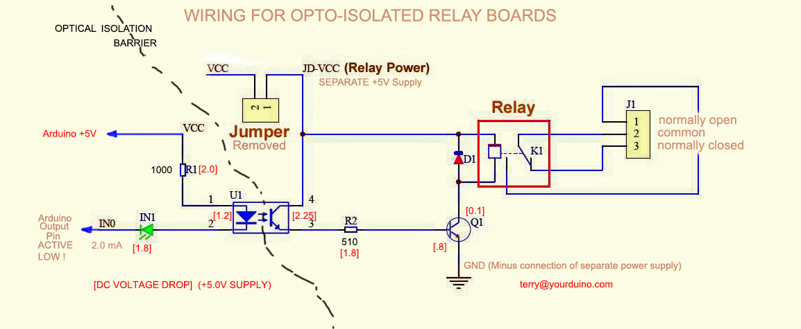
NOTE on 3.3V Signals:
It is possible to use these relay boards with 3.3V signals, IF the JD-VCC(RelayPower) is provided from a +5V supply and the VCC to JD-VCC jumper is removed. . That 5V relay supply could be totally isolated from the 3.3V device, or have a common ground IF opto-isolation is not needed. If used with isolated 3.3V signals, VCC (To the input of the opto-isolators, next to the IN pins) should be connected to the 3.3V device's +3.3V supply (Or the devices 5V supply if available, like BeagleBoneBlack). You should test with your 3.3V device to be sure. We will soon be testing with Arduino DUE , BeagleBoneBlack, Intel Galileo and Raspberry Pi which are 3.3V devices.
You can control a lot of different lights, water valves, and ventilation systems with relays like this. With some sensors and your Software Sketch ideas, an intelligent system may be born. NOTE: Sometimes switching these kinds of loads can cause Electromagnetic Interference, Arduino lockup etc. More information on handling these problems [/RelayIsolation is available HERE:]
Comments, Critiques, Suggestions welcome! terry@yourduino.com
zz

