StarterSet-Circuits-Pins-Bits
PINS...
BITS...
ONES and ZEROS...
HIGH and LOW...
... YOU'LL KNOW!!
OK, Fans, it's ELECTRICITY Time ! And, the weird thing about electricity is it's INVISIBLE! So we need to learn how to make it visible to us. Here's how to think about it:
5V, HIGH, GND, LOW:
DIAGRAMS:
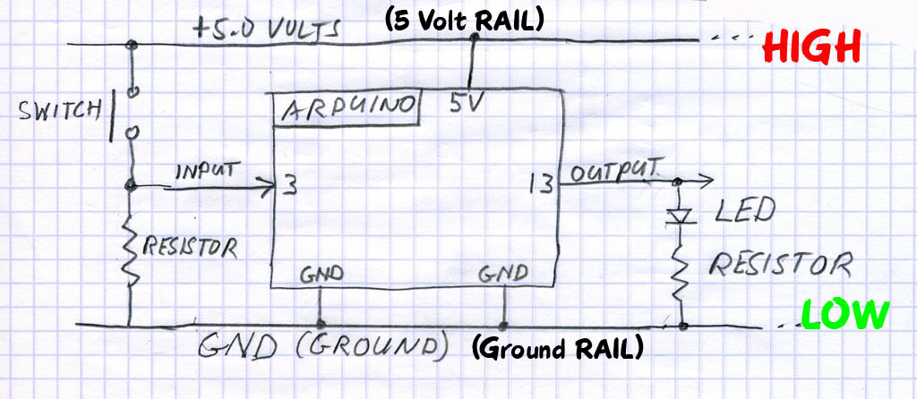
Often an actual circuit (like the YourDuino and Breadboard hookup) gets to be a confusing bunch of wires and components going in all directions. To keep our heads together, we draw Circuit Diagrams to show what we're trying to do. Notice the Symbols used in the diagram above for things like: SWITCH, RESISTOR, LED. And there are Labels on connections, like GND, INPUT, OUTPUT, ARDUINO etc.

  There's our theme music again: "Watch Closely Now"... In the diagram above, we have added a dose of reality: Arduino is powered (usually) by +5.0 Volts of DC (Direct Current).

  We show the +5.0 Volts connected HIGH on the top. Look closely at YourDuino.. find the PIN marked "5V". that's the one +5.0V power is connected to. Where does it come from?? (To start, from the USB cable from your computer to Arduino.)

  We show GND (Ground) connected LOW down on the bottom of YourDuino. Look at YourDuino (or a photo).. find the PIN marked "GND". ("Watch Closely Now" - There are actually 3 "GND" PINS).
RAILS !
As we mentioned earlier, the parallel lines of +5V HIGH on the diagram, and GND - LOW on the diagram are called "RAILS". Kind of like railroad RAILS across the top and bottom. Almost everything that happens on Arduino is between the +5V HIGH RAIL and the GND-LOW (0.0V) RAIL.
DIGITAL "SIGNALS":
When a PIN (or wire or connection) changes from 0 to 1, or 1 to 0, we say it is a SIGNAL. Kind of like someone raising up a flag or lowering it.
OUTPUT SIGNALS: An LED or Buzzer connected to to an Arduino OUTPUT can "signal" you that something has happened.
INPUT SIGNALS: If you push a button that changes an INPUT, you "signal" Arduino that something should be done.
BITS !
Oh, um.. what's a BIT anyway? It is a Binary InTeger which is a number which has only two possible values: 0 and 1. Each YourDuino Input or Output PIN is one BIT inside Yourduino. (A GROUP of 8 BITS is called a BYTE. Bet you knew that!).
DIAGRAMS:
OK, Look again at the diagram above:
The pushbutton switch causes the INPUT to change from LOW to HIGH, which is a "signal" to Yourduino.
Yourduino can change the OUTPUT from LOW to HIGH, causing electricity to flow through the LED, light it up and "signal" you.
OK, another one of those tekkie words:
DIGITAL: This means Arduino will use these Pins only as ON or OFF.
You will hear "Digital" things described three or four ways: but "0" and "OFF" and "LOW" mean the same thing. And "1" and "ON" and "HIGH" mean the same thing.
"DIGITAL" values
0 |
1 |
OFF |
ON |
LOW |
HIGH |
0.0 Volts(GND) |
5.0 Volts(5V) |
Let's listen to the way these terms are used by people talking about this Microcomputer Stuff:
When SOFTWARE inside the Arduino sets an OUTPUT PIN to a "1" it is "ON" and "HIGH" . Arduino connects the PIN to the HIGH RAIL which is 5.0V (5V).
When SOFTWARE inside the Arduino sets an OUTPUT PIN to a "0" it is "OFF" and "LOW". Arduino connects the PIN to the LOW RAIL which is 0.0V (GND).
Sorry for the multiple names for the same things, but those names are widely used, and it's time for you to know them...
PINS, BITS, ONES and ZEROS, HIGH and LOW... (Make Sense??)
No?? Please email terry@yourduino.com and ask questions and make suggestions...
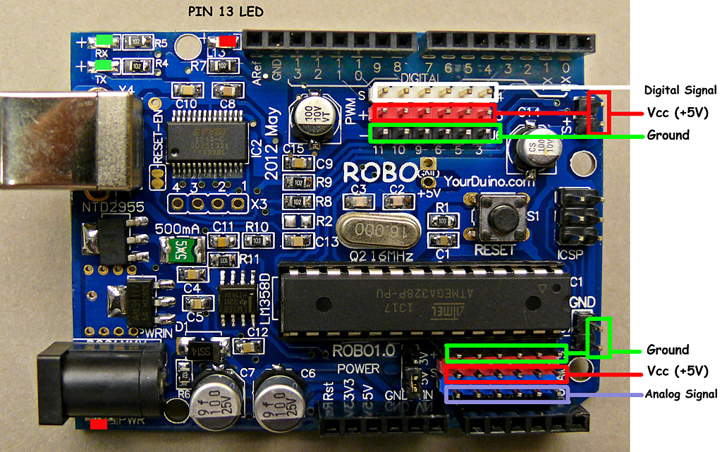
OK, time to stop talking and hook real things up to those INPUTS and OUTPUTS. Look at YourDuino again for a minute. You'll get to know it well:
Take a couple of minutes to look at it closely. If you haven't done much detailed electronics it looks like a jumble. But slow down and look at the different parts.
What's important to us first?? We need to connect stuff, so we'll look at the connectors.
All regular Arduinos have the same overall size and the same long black connector strips across the top and bottom edges. These are female sockets that pins can plug into. YourDuino has added two sets of 3-pin connectors to make it easy for you to connect things. Let's look at the details. First, here is the top connector:

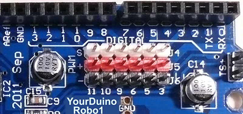
The Sockets (Places you can connect wires and devices to) are numbered 0 to 13 from right to left. These are the DIGITAL INPUT/OUTPUT connections. You can push wires or the pins on the end of wires into those "Black Holes" and connect them to many different devices.
We'll be looking at many of the different INPUT DEVICES and OUTPUT DEVICES you can connect to Arduino.
3-pin YourDuino Connectors:
NOTE: If you have a regular Arduino/YourDuino you can plug a [/SensorShield Sensor Shield] on top of it and have the same type of connectors.
YourDuino adds two sets of connectors to the usual Arduino arrangement. The DIGITAL Input/Output connector shown above has 3 rows of pins (White, Red and Black). Look at the labels on the left:
S (Signal) Is the White row in this photo. (Many YourDuinos have all black connectors, however)
+ (+5V RAIL) is the Red row
- (GND RAIL) is the Black row.
This arrangement is so that you can connect devices to YourDuino with a 3-pin cable that provides +5V and GND as well as the SIGNAL connection. Also there are plenty of 5V RAIL and GND RAIL pins now, not just the one 5V pin on regular Arduinos. Example: Look at the ServoMotor included in your kit. It is like those used in Radio Control models. It's 3-pin plug with black-red-white wires can plug directly on 3 pins in a vertical direction, and connect to GND, +5V and SIGNAL. Soon we'll plug your Servo in and try it out.
DIGITAL Input/Output Connector:
Look at the connector above. Notice that it is numbered: 11 10 9 6 5 3 . This means that those YourDuino pins are the ones made available on the 3-pin connectors. Also, those pins are all ones that have the capability for "PWM" which means "Pulse Width Modulation" and can be used to control the amount of power sent to an output device. We'll try that out soon.
ANALOG Input Connector:

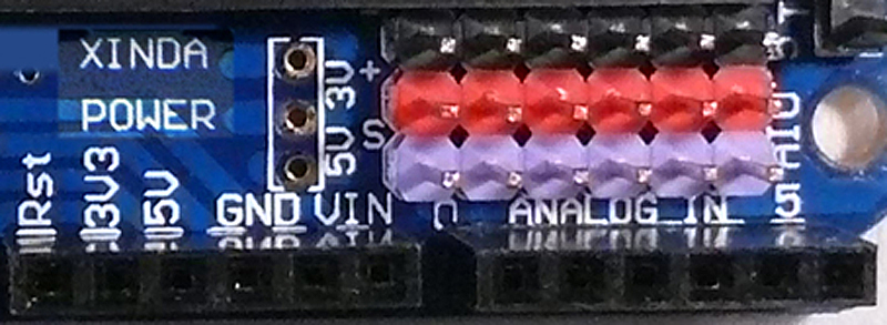
This row of black female sockets is the other part of the standard Arduino connectors. It includes voltage and GND pins, and also 6 ANALOG INPUT pins, labelled "0 ANALOG IN 5" which really means Analog Inputs 0 through 5. Analog inputs can be used to measure voltages, not just see HIGH=1 or LOW=0 like Digital Inputs. We'll use them in a while to measure things.
Again, YourDuino provides a set of 3-Pin connectors to make it easy for you to connect things. From Top to Bottom, there are 3 rows in the opposite order of those at the top. These are:
- (GND RAIL) is the Black row.
+ (+5V RAIL) is the Red row
S (Signal) Is the White row in this photo. (Many YourDuinos have all black connectors, however)
More about ANALOG INPUTS and other uses of these pins later.
