Popular-ICs
Popular IC's often used with Arduino:
NOTES:
- "2x or 4x, etc." means that there are multiple identical circuits that can be used within the same IC package.
- Words with a small Upward Arrow are Clickable inks Like This to more information.
- Most ICs have a printed or embossed DOT or MARK on their case that shows the location of Pin 1, or the end of the IC that has pin 1 (See LM324 and LM386 below).
- Pins are numbered CounterClockWise from pin 1 as seen from the top. (Aside: WHY CounterClockwise? Answer: Because Vacuum Tubes were wired clockwise from the bottom!)
- How To Read Device DataSheets (LINK)
ANALOG /INTERFACE IC'S
LM393 2x comparator


A comparator is a device that compares two voltages and switches its digital output to indicate which is larger. It does it's comparison in the Analog domain and outputs it's result as a Digital value (1 or 0, High or Low). NOTE: This chip is the same as the LM339 but has 2 comparators.
LM293 DATA SHEET: Media:lm293-n.pdf
COMPARATOR TUTORIAL:
COMPARATOR CIRCUITS:
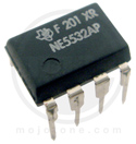
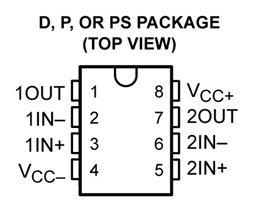 NE5532 2x low-noise opamp


This IC contains two high-quality Operational Amplifiers. These amplifiers can be used in many applications in both AC and DC circuits. They are often used in professional audio systems as microphone preamplifiers etc. Their voltage gain can be set easily with two resistors.
Wikipedia has an excellent section showing Operational Amplifier Applications.
NE5532 DATA SHEET: Media:NE5532-D.PDF
NE5532 CIRCUITS:
LM324 4x opamp single supply

This IC contains 4 Operational Amplifiers. It is optimized for operation from a single power supply and works well with a +5V supply for signals that work in that reduced voltage. This is a very popular Chip used in many applications.
LM324 DATA SHEET: * Media:LM324.pdf
LM386 Audio amp low-voltage


This chip is widely used when medium-loud audio from a speaker or headphones is needed. Below is an example circuit.

LM386 DATA SHEET: Media:LM386.pdf
NE555 Timer-General purpose


The 555(Wikipedia) is one of the most versatile and popular Chips ever invented. The diagram on the right shows it's pinout and a useful diagram of it's functions. The 555 consists of a flip-flop that can be switched from OFF to ON, and a strong output driver that can source or sink 200 mA. It has two comparators (see above) that determine when the flip-flip is turned on or off. There are three 5K resistors in series inside the chips, connected from Vcc to Gnd and to the two comparators. By connecting various resistors and capacitors to the chip it can be used as a timer, as an oscillator, a driver for power FETs, a line driver, and for many other functions. Below are links to some favorite 555 sites showing circuit diagrams and functions.
555 DATA SHEET: Media:555.pdf
LOTS more 555 info and circuits: See THIS page
555 TIMER RESISTOR/CAPACITOR CALCULATOR
Random Nerd 555 TUTORIAL

555 AS POWER FET DRIVER (above): A 555 is a good cheap driver for the high capacitance of a power NFET gate. The example diagram shows a 12 volt supply to drive Power FETs that have threshold voltages of 4 or 5 volts and need the gate driven to +10V or so for typical high current applications. NOTES:
- The resistor from pin 5 to ground sets the input voltage thresholds for TTL / 5V signals such as Arduino.
- This circuit INVERTS the input signal, so Arduino PWM will "work backward". Or: Fix It In Software.
- Use a BIPOLAR version 555, NOT a CMOS version. Examples: NE555N etc. for high output capability.
- NEED good bypass capacitors from 555 Vcc to Ground. Recommend .1 uf in parallel with 1 to 3.3 uF to handle the high output currents in the 555.
555 TRIVIA: Input Priorities of the 555
If you are using the 555 to do something unusual, you might need to know this:
Usually , when the 555 sees the TRIG pin go low (lower than half the CONT voltage), that sets the flip flop, and the output goes high.
Usually , when the 555 sees the THRESH pin go high (higher than CONT voltage), that clears the flip-flop and the output goes low.
Usually , (in most 555 circuits) the TRIG pin will be high again (higher than half of CONT) before anything happens at THRESH. But, if you are doing something Unusual, you might have a low signal at TRIG, and a signal at the THRESH pin that is higher than CONT at the same time .
If that happens, you are telling the 555 both to set its output high, and to set its output low. In this case,TRIG being low wins and the output is set high .
In other words, TRIG is higher priority than THRESH. This also means that if TRIG is held low, THRESH is ignored. One other important thing to know is that RES is the highest priority. RES being low always makes the output go low , no matter what is happening at TRIG and THRESH. TRIG and THRESH are both ignored if RES is low.
We KNEW you wanted to know that :-)
OPTO-ELECTRONIC IC'S
PC817 Opto-Isolator


This IC has an internal LED that can be driven from an Arduino output (with a series resistor of approximately 220 ohms). It has a phototransistor output which is turned ON when the LED is ON. (See pinout diagram on the right). There is no electrical connection between the input and output; only light crosses the barrier inside. This is excellent for connecting devices that have no common ground connection or operate at different voltages. This IC has a "Current Transfer Ratio" (ratio of LED current to output transistor current) of about 100.
PC817 DATA SHEET: Media:LTV-817-Optoisolator.pdf
4N25-35 Opto-Isolator


This is a popular Opto-Isolator electrically similar to the PC817 above.
4N25-35 DATA SHEET: Media:4N25-35.pdf
MOC3061 Opto-TRIAC (0-crossing)


This is another Opto-Isolator with an internal LED you can drive from an Arduino output. (Recommended series resistor: 150 to 220 ohms). This IC is designed to drive larger TRIACs (AC Power Line switching devices) while isolating the Microcomputer from the Power Line. It also switches at the points when the AC Power line is at Zero volts, greatly reducing noise and transients.
MOC3061 DATA SHEET: Media:MOC3061.pdf
OTHER:
MAX485 RS485 Transceiver


This IC is good for small networks or connecting to other RS485 devices. Multiple Transceivers can connect to the same 2-wire bus.
More RS485 Information Here:
And here: http://www.maximintegrated.com/app-notes/index.mvp/id/723
MAX485 DATA SHEET:Media:MAX485.pdf
ULN2003 7x Darlington Power Driver

This IC is used for driving devices like large LEDs, small motors, small Stepper motors, relay coils, etc. up to a voltage of 50V and a current of 500 mA for each output. Outputs can be paralleled for higher currents. It has "Open Collector" outputs which means it acts like a switch with one side connected to ground, also called a "Low Side Switch". It has built-in reverse-voltage protection diodes. There are 7 identical circuits.
ULN2003 DATA SHEET:Media:uln2003.pdf/329213434/uln2003.pdf
1N4148 Fast-Switching Small Silicon Diode


This is a general-purpose diode rated at 100V and 300 mA. The end with the marked band is the "Cathode" which is the straight bar part of the diode symbol. A diode conducts current when the Anode is more positive than the Cathode, and blocks reverse current. More Information Here:
1N4148 DATA SHEET:Media:1N4148.pdf
1N4007 (1 Amp 1000V) DATA SHEET: Media:1N4001_F11.pdf
1N5408 (3 Amp 1000V) DATA SHEET: Media:1N5408.pdf
Digital ICs
These ICs operate at the 5V "CMOS/TTL" signal levels used by Arduino. They provide various digital logic functions.
74HC14 6x Inverter


Schmitt_trigger Schmitt-Trigger
This very useful IC has 6 "Inverters" which means if the input is a 1 the output is a 0 and vice versa. Sometimes that function alone is needed, but this chip has two other common uses:
- Make a weak signal into a strong one. (It takes very little input current and provides a strong output).
- Remove noise from a noisy signal. (It has a "schmitt-trigger" property which means the input must go above a higher threshold to be seen as a 1 and a lower threshold to be seen as a 0. This is called "hysteresis". )
What if you just want to use those capabilities but not Invert the signal? Just put another inverter in series with the first one.
This chip can also be used to create digital delays, oscillators and other functions.
74HC14 DATA SHEET: Media:74HC_HCT14.pdf
74HC595 Serial-In-Parallel-Out Expander


This IC is a Shift Register so that 8 bits of data can be 'shifted' into it over just 2 wires. This is often used to add more functional Digital Outputs to Arduino. It is most often controlled by the Arduino standard function shiftOut. See the Reference Page. [1]]
Multiple 74HC595 chips can be connected in series so that the same 2 or 3 Arduino pins can control 8 or 16 or 24 etc. output bits.
Arduino shiftOut Tutorial
74HC595 DATA SHEET: Media:74hc595.pdf
74HC165 Parallel-In-Serial-Out Expander


This IC is also a Shift Register. Now, 8 bits of data on Inputs (D0 to D7) can be 'shifted' into Arduino over just 2 wires. This is often used to add more functional Digital Inputs to Arduino. It is most often controlled by the Arduino standard function shiftIn.
See the Reference Page. Multiple 74HC165 chips can be connected in series so that the same 2 or 3 Arduino pins can read in data from 8 or 16 or 24 etc. input bits.
Arduino shiftIn Tutorial (Note: This tutorial shows a different chip.)
74HC165 DATA SHEET:Media:Sn74hc165.pdf