Arduino-testing
Testing Arduino Boards
Contact Terry King: terry@yourduino.com
NOTE: Photos Updated..Terry
YourDuino.com Arduino Board TEST
Tests all Arduino I/O and Analog pins
This test assumes that pins 0 (RX Data) and 1 (TX Data) are OK if programs can be loaded, and that pin 13 is OK if it's attached LED can be blinked. Pin 13 is not tested for current sink ability.
Test progress and pass-fail results are sent to the Serial Monitor. At the end of test, Pin 13 LED is blinked very slowly for Pass and quickly for Fail.
This test works with a "Test Shield" that is plugged on top of the Arduino under test. This shield has a common isolated connection point. The Common Point has 17 220 ohm resistors connected to every digital pin from 2 to 12, and to every analog pin from 0 to 5. It also has two 100,000 ohm resistors which connect it to Ground and +5.0 volts, forming a voltage divider that sets the common point to 2.50 volts when all pins are in the reset high-impedance input condition. This is read by A0 to initially test if any of the pins are "stuck" or "leaking", which will pull the common point away from 2.50 volts.
The Test Shield layout on Proto Boards will be shown below, and the Arduino Software will be linked to.
Next, pins 3 thru A5 are tested by setting them High or Low against an opposite load presented by pin 2. Each pin must be able to source and sink at least 10 ma to bring the common point near 2.50 volts.
If pin 2 fails, all other pins will fail.
Then, A0 thru A5 are tested individually with voltages near 0.0, 5.0, 2.5 and a few others, using the resistors connected to the digital pins to make various voltage dividers.
TEST SOFTWARE:
The Arduino Test Software can be downloaded here:(CLICK)
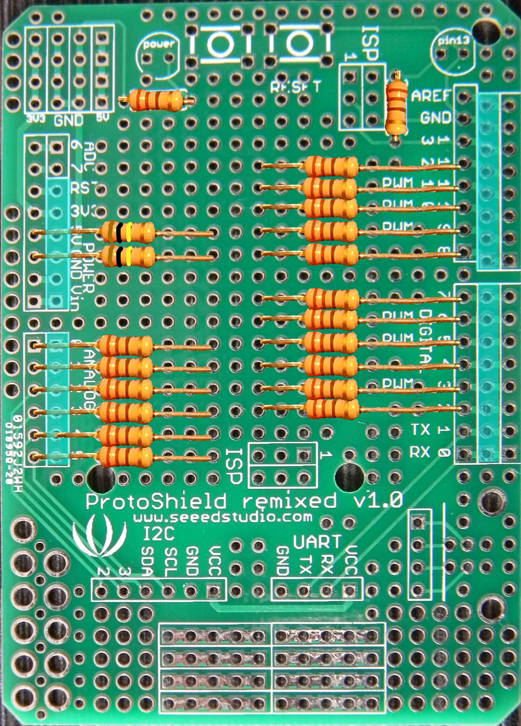
The Test Shield has been built on a couple of different Protoboards. Here are views of the version on a SeeedStudio Protoboard which you can see on Seeed's site here: (CLICK)
You may also want to populate the LEDS and the RESET switch.
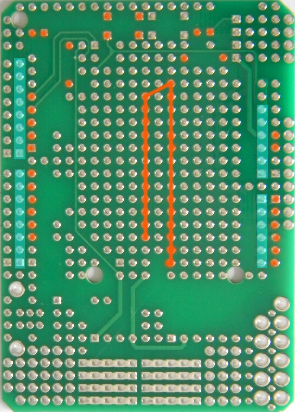
Here's the back view.
Note: that all the center resistor connections go together to make the "Common Point".
Note: The Blue overlay areas are where the pin strips are soldered that plug below into Arduino.
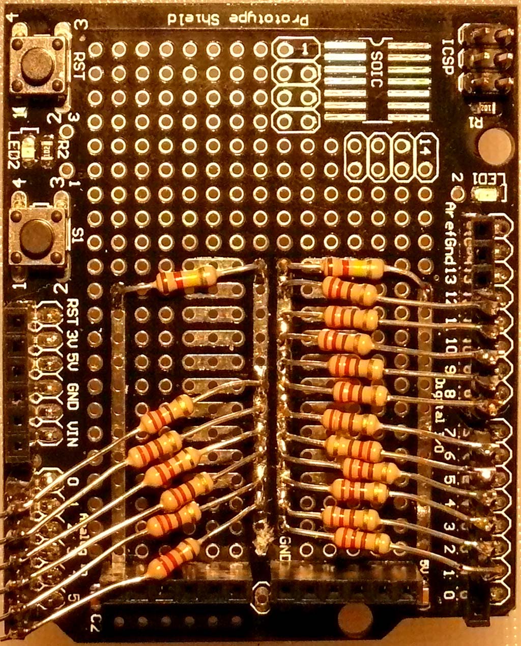
And here's another version on a Protoboard that already had sockets etc.
NOTE! It's tempting to just push the resistor leads into the sockets. Don't! The connections are not reliable. You can see we inserted pin strips in the sockets and soldered the resistors to them.
OTHER BIG NOTE!: The two long traces in the center, used to create the Common Point are originally tied to +5 and Ground. You need to look carefully at the top and bottom of the board just at the end of those strips, find the trace connecting them to +5 or Ground and CUT it carefully with a small knife, just enough to disconnect those strips from +5 or Ground. TEST with a meter etc. to be sure..
Just above, in the bottom just to the left of the "GND" label you can see where a trace was cut. There is a similar trace on the bottom of the board, to the other strip.
This design and software is licensed under a Creative Commons Attribution-Noncommercial-Share Alike 3.0 License:http://creativecommons.org/licenses/by-nc-sa/3
The test program puts out results to the Arduino Serial Terminal that looks like this:
---------------------( COPY )--------------------------
Arduino Board Test V1.07
Arduino-Direct.com terry@arduino-direct.com
--- TEST START ---
TEST 001 - Any stuck pins??
VoltsRead = 2.50 -- OK!
TEST 002 - Digital Pins Source Current
PIN-3 PIN-4 PIN-5 PIN-6 PIN-7 PIN-8 PIN-9 PIN-10 PIN-11 PIN-12
2.49 2.50 2.49 2.50 2.50 2.51 2.51 2.52 2.53 2.44
-OK- -OK- -OK- -OK- -OK- -OK- -OK- -OK- -OK- -OK-
TEST 003 - Digital Pins Sink Current
PIN-3 PIN-4 PIN-5 PIN-6 PIN-7 PIN-8 PIN-9 PIN-10 PIN-11 PIN-12
2.55 2.54 2.53 2.52 2.52 2.52 2.51 2.49 2.49 2.58
-OK- -OK- -OK- -OK- -OK- -OK- -OK- -OK- -OK- -OK-
TEST 004 - Analog Pins Source Current
PIN-1 PIN-2 PIN-3 PIN-4 PIN-5
2.47 2.49 2.49 2.50 2.51
-OK- -OK- -OK- -OK- -OK-
TEST 005 - Analog Pins Sink Current
PIN-1 PIN-2 PIN-3 PIN-4 PIN-5
2.52 2.50 2.50 2.49 2.48
-OK- -OK- -OK- -OK- -OK-
TEST 006 - Analog Pins A0 to A5: A to D (About 2.50 V)
PIN-0 PIN-1 PIN-2 PIN-3 PIN-4 PIN-5
2.48 2.48 2.48 2.48 2.48 2.48
TEST 007 - Analog Pins A0 to A5: A to D (About 3.33 V)
PIN-0 PIN-1 PIN-2 PIN-3 PIN-4 PIN-5
3.32 3.32 3.32 3.32 3.32 3.32
TEST 008 - Analog Pins A0 to A5: A to D (About 1.66 V)
PIN-0 PIN-1 PIN-2 PIN-3 PIN-4 PIN-5
1.65 1.65 1.65 1.65 1.65 1.65
TEST COMPLETE
Please send comments and suggestions to: terry@yourduino.com


