Opto-Switch
Jump to navigation
Jump to search
Opto-Switch

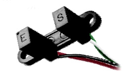
This shows how to use the OPB810W55 Opto-Switch. It looks like this:
The "E" (EMITTER) side is the Infrared (invisible) LED which shines across the gap.
The "S" (SENSOR) side is a phototransistor that turns ON when hit by the light beam.
(The Datasheet is here): Media:OPB810.pdf
The connections are as follows:
Emitter LED:
- BLACK (BK) is - (minus) or GND
- RED (RD) is + and should go through a 220 ohm resistor (approximately) to +5 Volts or an Arduino Output set to HIGH.
Sensor PhotoTransistor:
- GREEN (GN) is - or GND
- WHITE (WH) is + and should be connected to +5 V through a 10K (approx) resistor. It is also connected to an Arduino Digital Input. This input will be LOW when the light beam is seen by the Sensor, and HIGH when the light beam is blocked by something.
Here's a test program for Arduino:
/* YourDuino SKETCH TEMPLATE
 Used Opto-Switch OPB 810W55
 terry@yourduino.com */

/*-----( Import needed libraries )-----*/
/*-----( Declare Constants )-----*/
/*-----( Declare objects )-----*/
/*-----( Declare Variables )-----*/
int IR_LED_PIN       = 2;
int IR_DETECTOR_PIN  = 3;
int TestLED          = 4;


void setup()   /****** SETUP: RUNS ONCE ******/
{
  Serial.begin(9600);
  pinMode(IR_LED_PIN, OUTPUT);
  pinMode(TestLED, OUTPUT);
  digitalWrite(IR_LED_PIN, HIGH); // Turn on Opto LED

}//--(end setup )---


void loop()   /****** LOOP: RUNS CONSTANTLY ******/
{
  if  (digitalRead(IR_DETECTOR_PIN) == 0)  //Beam is Seen
  {
    digitalWrite(TestLED, HIGH);
    Serial.write("H");
  }
  else
  {
    digitalWrite(TestLED, LOW);
    Serial.write("L");
  }
delay(200);
}//--(end main loop )---

/*-----( Declare User-written Functions )-----*/


//*********( THE END )***********