RobotKitUnpacking
NOTE: Still needs some editing for new wiki!
UNPACKING AND CHECKING YOUR ROBOT KIT PARTS:
Below is a look at the parts contained in your Robot Kit. To begin with all you need to take out are:
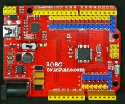
- The YourDuino RoboRED Microcomputer and its USB cable
- The Servo Motor
- The Ultrasonic Distance Sensor
- The Flat "Rainbow" cable
We will be using those parts to get the Arduino IDE software downloaded and running, and to learn the basics of programming Arduino. Then we will learn a bit about the Servo Motor and Ultrasonic Distance Sensor, and make them work.
Later, you will work on building the Robot Base, with Motors, wheels, Battery Pack etc.
YourDuino RoboRED: Upgraded Arduino Uno-compatible Microcomputer
With built-in 3-pin I/O connectors, higher current 5.0V and 3.3V supply. With ATMEGA328 Processor. See: The RoboRED HERE
Ultrasonic Distance Sensor (Looks for things in the way). This sensor sends out ultrasonic beeps that cannot be heard by humans. Then it listens for an echo to return and calculates the distance to objects in front of it. Extensive educational materials on Ultrasonic sensors are available: HERE
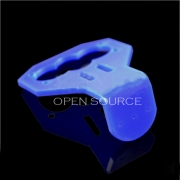
Plastic Bracket to hold Ultrasonic Sensor on top of Servo
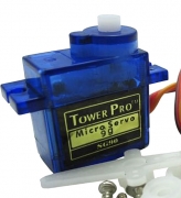
Servo (Points the Ultrasonic Sensor in different directions). The servo positions its shaft over a range of about 180 degrees. The position is controlled by a signal from the RoboRED. In our software, the servo points the ultrasonic sensor to "look" left, then center, then right.
40-wire Rainbow Cable (Connect the parts). The 40 wires in this cable will be separated into strips to connect different parts of the robot. Colors will be selected to make connections clear.
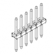
Pin Strips (Connect the parts). In cases where the rainbow cable needs to connect to female sockets, these pins can be used to make the connection.
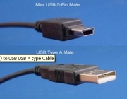
USB Cable This cable plugs into the silver connector on the edge of the RoboRED. It is used to upload software sketches to the RoboRED and to receive test information from the test sketches that individually test the parts of the robot.
Get those parts above out on your table, and then go back to RobotKitMenu-1#GS Getting Started:
Wait until later to use these following parts to build the Robot Base.
Building the Robot Base
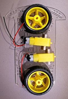
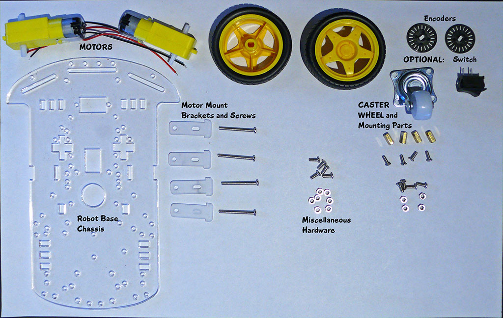
Robot Chassis with 2 DC motors and 2 wheels
(Not pictured: caster wheel and small package containing: screws, nuts, standoffs for caster wheel, motor mounting brackets, optional power switch and optional encoder wheels.)==
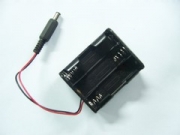
Battery Pack for 6 AA batteries (We suggest using rechargeable NiMH batteries)==
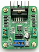
Motor Driver Board (Controls motors' speed and direction)
The board has metal "stand-offs" attached at the 4 corners. The motor driver board you receive may have the stand-offs already attached or you may need to screw them in place.
The motor driver board uses a LM298N chip and heat-sink to control power from the battery pack to the 2 DC motors. Signals from the RoboRED can control the direction and speed of each motor.
Blue #22 Wire to mount the Servo and the Ultrasonic Sensor You can cut pieces of this wire (strong scissors or wirecutters) to attach parts to the robot chassis.
Double-Ended Screwdriver You can plug the metal piece into the handle in 2 ways. You can use either the flat blade and/or the Phillips X-shaped blade. NOTE: Appearance may vary from this photo..
Robot Base Chassis Hardware Later when you start to build the Robot Base it would be good to lay out these parts and become familiar with them.
VELCRO WILL BE SUPPLIED TO MOUNT RoboRED, Motor Driver, Servo and Battery Case.
- Caster Wheel. This swivels around to allow robot movement in any direction.
- Caster standoffs: 10mm long brass metal (4). These are threaded inside so screws can be used to hold the Caster Wheel in place at the right level.
- Encoder discs (2) Not Used in this kit. These can be used with more complex software to measure the wheel rotation.
- Long machine screws: 30mm (4) use to attach motors and brackets.
- Power Switch (optional): This may be difficult to push into place in the rectangular cutout in the chassis. Wiring details are not available at this time.
- Motor Mounts (4) will attach the motors to the chassis.
- Assorted Machine Screws and Nuts.
- Screwdriver: Double-ended - both flat and "Phillips" ends. (See Photo)
If you would like to try a simple example with a few of these parts before you start building the robot, see the exampleON THIS PAGE.
  To start building your robot,Click HERE.
