Servos
SERVOS: Information - Electrical and mechanical
Also see ESC "Electronic Speed Control" and Example Software Sketches below.
(CREDITS: John at http://www.rchelicopterfun.com/)
(ALSO SEE the "SERVO DATABASE" HERE)
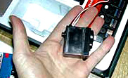
Servos are small box-shaped electro-mechanical devices that contain a DC motor, electronics to control the motor from a signal, a gear system to produce slow/strong output to a shaft, and a position feedback potentiometer. There are a variety of sizes and weights, of similar construction. They are widely used in Model cars and airplanes, and can cost as little as $3.50
Servos usually come with several different arms you can attach depending on your design. Usually you use a Servo to position something, like steering direction, arm/leg movement etc.
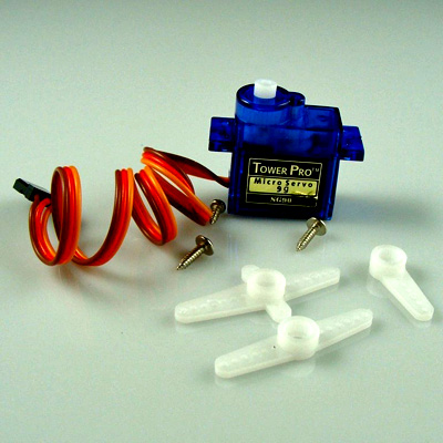
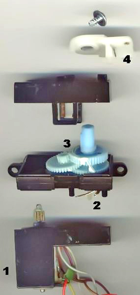
For most servos the position angle of the servo is controlled by the length of the pulse in milliseconds (usually between about 1.00-2.00ms). 1.50ms is usually Center, or Stopped (For Robot Servo).
What you can do with 8 servos!
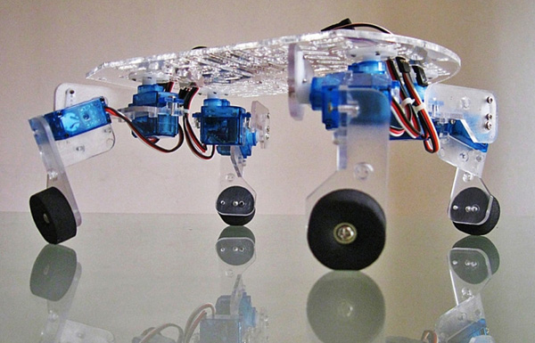
Above photo is of a Quadbot Chassis .]
Now, all RC servos have a three wire connector. One wire supplies positive DC voltage – usually 5 to 6 volts. The second wire is for power ground, and the third wire is the signal wire. The controller “talks” to the servo through this wire by means of a simple on/off pulsed signal. They can plug directly into the 3-pin connectors on a YourDuino RoboRED or a SensorShield. The RoboRED can provide up to 2 amps at 5V and so can run 4 or more servos, depending on the servo type and how they are controlled. Servos take much more current just as they start a large move.
Sizes
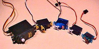
Servos basically come in 3 different sizes (micro, standard, and giant or 1/4 scale) to accommodate the type of RC model or other application they are being used in. There are slight variations depending on the specific application but for ease of explanation, these 3 sizes cover most of the servos out there.
CONNECTIONS:
- wire colors may vary!
- Servo Black or Brown to Gnd.
- Servo Red or Orange (Center wire) to +5V
- Servo White or Yellow to Signal (Pin 9)
Speed and Torque Ratings
Other than physical size, the next item that all RC servo specifications indicate is speed and torque.
Speed is a measurement of the time it takes the servo to rotate a certain number of degrees. This has been standardized in most specifications to 60 degrees; In other words, the time it takes the servo wheel to turn 60°. The smaller the number, the faster the servo is. For example a 0.12 sec/60° servo rating means it will take 0.12 seconds to rotate the servo arm or wheel 60°. This would be twice as fast as a standard speed servo that is rated in the 0.24 sec/60° range. A RC helicopter tail rotor specific servo will have speeds as fast as 0.06 sec/60°.
Torque defines the maximum amount of rotational force the servo can apply. This specification is measured in force at some distance from the center of rotation. This is typically measured in ounce-inches of foot-pounds or in kilograms-centimeter (kg-cm). The larger the number, the more force the servo can exert. A typical standard servo will have a torque rating around 40 oz-in. A high torque specific servo can have torque values well over 200 oz-in.
So what exactly does 40 ounce-inches mean?
Well if you had a servo arm that was one inch long on your servo it would be able to produce 40 ounces of pull or push force at the end of the servo arm before stalling. If you had a 1/2 inch servo arm what do you think the force would be? Yup, 80 ounces of force. How about a 2 inch arm, 20 ounces of force - easy huh?
We should also point out that both speed and torque specifications are usually given for the two common voltages used for receiver battery packs. 4.8 volts for a 4 cell battery pack and 6.0 volts for a 5 cell battery pack. See examples in the table below. Also see the Servo DataBase.
Although it exceeds many specifications, some robot designers use 7.2V LiPo batteries to drive both Arduino (through the external power connector) and Servos.
ROBOT Servos:
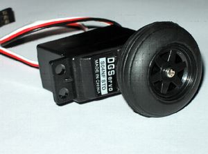
"Robot" Servos are basically the same design and motors and gears but are able to rotate continuously. The same pulse signal is used, but now it controls speed and direction. The photo shows one that comes with a wheel attached. It is possible to modify some regular servos to make them into Robot Servos.
Google " mod modify servo continuous"
NOTE: Servos that can rotate continuously have no absolute position information available. The exact Pulsewidth that makes the motor stop is usually not exactly equal to the "90 degrees" value of a positional type servo. If you want your robot to stop completely you will have to determine the needed value. (We will add example code to help with that).
Comparison Table: Robot Servos
| Comparison Table: Robot Servos (Continuous Rotation) |
|||||||||
| Model Number |
Weight |
Weight |
Size(In) |
(Size(Metric) |
Torque Rating 4.8V |
Torque Rating 6.0V |
Rotation Speed 4.8V |
Rotation Speed 6.0V |
Gears: Metal/Plastic |
| SM-S4303R Analog |
1.55 oz |
(44.0 g) |
1.65×0.81×1.56 in |
(42.0×20.5×39.5 mm) |
4.8V: 45.8 oz-in (3.3 kg-cm) |
6.0V: 66.7 oz-in (4.8 kg-cm) |
4.8V: 0.17 sec/60° |
6.0V: 0.14 sec/60° |
Both |
| SM-S4306R Analog |
1.55 oz |
(44.0 g) |
1.65×0.81×1.56 in |
(42.0×20.5×39.5 mm) |
4.8V: 69.4 oz-in (5.0 kg-cm) |
6.0V: 86.1 oz-in (6.2 kg-cm) |
4.8V: 0.20 sec/60° |
6.0V: 0.17 sec/60° |
Both |
| SM-S4309R Analog |
2.12 oz |
(60.0 g) |
1.65×0.81×1.56 in |
(42.0×20.5×39.5 mm) |
4.8V: 109.7 oz-in (7.9 kg-cm) |
6.0V: 120.8 oz-in (8.7 kg-cm) |
4.8V: 0.20 sec/60° |
6.0V: 0.17 sec/60° |
Metal |
| SM-S4315R Analog |
2.12 oz |
(60.0 g) |
1.65×0.81×1.56 in |
(42.0×20.5×39.5 mm) |
4.8V: 201.4 oz-in (14.5 kg-cm) |
6.0V: 213.9 oz-in (15.4 kg-cm) |
4.8V: 0.19 sec/60° |
6.0V: 0.16 sec/60° |
Both |
EXAMPLE ARDUINO SERVO CONTROL SKETCHES:
These are two example sketches. ServoSweep simply moves a servo back and forth over much of it's travel. ServoPotPosition lets you connect a potentiometer and use it to control the servo position.
Both of these will work with a Robot Servomotor and will control the motor direction and speed.
SKETCH EXAMPLE:
YourDuinoStarter-ServoSweep
EXAMPLE SKETCH: YourDuinoStarter-ServoPotPosition
Detailed Servo Information:
(From John at http://www.rchelicopterfun.com/) for those who want more details. This is aimed mainly at servos used in RC Helicopters, but the technical information applies to all servos.
And POLOLU has THIS nice discussion about Servos
Digital Servos vs. Analog Servos
Up to just a few years ago, the only RC servos available were analog, but now we have digital. To answer the question of which is better for RC helicopters or planes and cars for that matter – let’s look at how each work and the choice will be pretty obvious.
First off, there is no physical or main component difference between a digital servo or analog servo. The servo case, motor, gears, and even the feed back potentiometer all have the same functions and operations in both types. The difference between the two is in how the signal from the receiver is processed and how this information is used to send power to the servo motor.
Analog Servo Operation
An analog RC servo controls the speed of the motor by applying on and off voltage signals or pulses to the motor. This voltage is constant (the voltage of the receiver battery pack, voltage regular, or BEC to be exact - 4.8 to 6.0 volts).
This Pulse Width Modulation technique is internal to the little servo itself and has nothing to do with Arduino PWM capability. The internal servo PWM frequency is standardized to 50 cycles a second. The longer each on pulse is, the faster the motor turns and the more torque it produces. This is the same way the speeds of most motors are controlled. For instance, if you have a ceiling or exhaust fan in your house that is controlled with a variable rotary dial speed switch; the fan motor is not given lower and higher voltages to adjust the speed. The speed switch simply cycles the 120 volts to the fan motor on and off many times a second. The longer each on pulse is, the faster the fan runs. This is also the same way electronic speed controllers for electric RC helicopters , planes, cars, and boats work.
Now back to our analog RC servo. At rest, there is no voltage going to the motor. If a small transmitter command is given or some external pressure is applied to the servo horn forcing it off neutral, a short duration voltage pulse will be sent to the motor. The larger the stick movement or potentiometer movement, the longer this "on" pulse will be in order to move the servo quickly to the desired position. Remember me saying that these voltage pulses are sent 50 times a second. This means that in one second, there are 50 windows that last 20 milliseconds each (50x20 = 1000 ms = 1 second). The longer each on voltage pulse is in each of these fifty 20 millisecond windows, the faster the servo motor turns and the more torque it produces.
I just included this info for those of you who really want to know what makes a servo tick. You don’t have to understand all that however, as long as you understand that during small amounts of stick movement or when external forces are applied forcing the servo off its neutral or holding position; only a short duration voltage pulse will be sent to the servo motor every 20 milliseconds. With large stick movements, a long voltage pulse will be sent every 20 milliseconds to the servo motor.
As you can imagine, a short power pulse every 20 milliseconds doesn’t get the motor turning that quickly or allow it enough time to produce much torque. This is the problem with all analog servos; they don’t react fast or produce much torque when given small movement commands or when external forces are trying to push them off their holding position. This area of slow sluggish response and torque is called deadband.
Much of RC control, especially with RC helicopters is done with small quick stick movements moving the servo back and forth in very small increments. There are also many changing loads on the rotor system (both main and tail) that are always trying to force the servo off its hold position as well. Don’t forget about the gyro either. The new heading hold gyros or electronic flybarless systems are sending hundreds of small correction changes to the RC servos every second.
If I did a good job at explaining all this, you should realize by now that much of RC helicopter control and movement actually happens within the deadband area of an analog servo.
This is not really that big of deal for slow human response times, but as I mentioned, a problem for lightning fast gyros and electronic flybarless systems or advanced 3D pilots with cat like reflexes.
Digital RC Servo Operation
Digital servos to the rescue! Like I said before, a digital servo has all the same parts as an analog servo, even the three wire plug that plugs into the receiver is the same. The difference is in how the pulsed signals are sent to the servo motor.
A small microprocessor inside the servo analyzes the receiver signals and processes these into very high frequency voltage pulses to the servo motor. Instead of 50 pulses per second, the motor will now receive upwards of 300 pulses per second. The pulses will be shorter in length of course, but with so many voltage pulses occurring, the motor will speed up much quicker and provide constant torque.
Incidentally, if you have ever wondered why digital servos "sing" when very light force loads are placed on them, what you are hearing is the short high frequency voltage pulses acting on the motor.
The result is a servo that has a much smaller deadband, faster response, quicker and smoother acceleration, and better holding power. You can test this very easily by plugging in a digital servo and an analog servo to your receiver. Try to turn the servo wheel off centre on the analog RC servo.
Notice how you will be able to move it slightly before the servo starts to respond and resist the force - it feels a bit spongy.
Now do the same thing with the digital RC servo. It feels like the servo wheel and shaft are glued to the case – it responds that fast and holds that well. Now nothing is perfect and this increase in speed, torque, and holding power does come with a small disadvantage. Power Consumption! Yup, digital servos are power hungry. All those hundreds of power pulses per second use up more battery power than an analog servo would. This really is not that much of a problem these days since battery packs have at least double or triple the capacity of what the same size/weight pack had just a few years ago.
So yes, digital RC servos are much better than analog. You can still fly a RC helicopter with analog servos, but once you switch over to digital, you will likely never go back. Don’t forget about that heading hold gyro or electronic flybarless systems – they need to be paired with fast digital servos to work correctly – no exceptions!
One last point I should clarify with this whole analog/digital RC servo discussion. Remember those speed and torque specifications I talked about earlier... You will find analog servos that have better speed and torque ratings than some digital servos; so why not get one of them over a more expensive slower digital?
Remember, the analog servo is slow to respond and provides little torque during small, fast command inputs. Those good looking specifications are given at full stick movement when the servo has ramped up to full speed and torque. The slower spec digital servo in this case will still provide much more speed and torque where it is needed most.
Coreless & Brushless Servo Motors
Most low cost and standard servos (analog or digital) use what is called a 3 pole electric motor. This is just a standard 3-pole wire wound DC motor – the most common type of DC motor in existence. One step up from the 3 pole is the 5 pole servo motor. As you can imagine, two more wire windings will give a 5 pole motor quicker acceleration and more torque on start up.
You know by now the faster the servo ramps up to speed and the more torque it produces; the better it is for most applications. Well, improving the electric motor itself will produce more speed and torque too; coupled with digital technology, the resultant speed and torque are indeed impressive.
Coreless Servo Motors:
A standard 3-pole wire wound servo motor uses a steel core with wires wound around the core, this core is then surrounded by permanent magnets.
As you can imagine, the core and all that wire weighs a fair bit. When voltage is applied to turn the motor, it has to first overcome this weight to get things turning – it is slow to accelerate. Once up to speed, it also continues to turn for a while when the voltage is removed – it is slow to decelerate.
In a Coreless design, the heavy steel core is eliminated by using a wire mesh that spins around the outside of the magnets. This design is much lighter resulting in quicker acceleration and deceleration. The result is smoother operation, more available torque, and faster response time.
Brushless Servo Motors
The latest advancement is to use a small brushless DC motor in the servo. This is the exact same principle and has the same advantages as larger brushless DC motors that are used in electric RC helis, planes, and cars. There are no brushes that add drag or can wear out. Brushless motors are more efficient, provide more power, speed, and acceleration - once again raising the bar on the level of speed, torque, response time, and smooth operation.
RC Servo Bearings, Metal Gears, & Water Resistance
These last few points are pretty basic.
Bearings:
You will notice when servo shopping, many specifications list if the servo has bearings and the number of bearings – usually 1 or 2. These bearings are used on the main servo output shaft instead of a simple bushing. The advantages of having ball bearings on the output shaft in a servo are pretty much the same as I talked about in the Bearing Section of best RC helicopter features – less friction and slop. Because of the many vibrations and mechanical loads placed on the servo in RC helicopters, non bearing servos do develop slop very quickly and of course this makes control more sluggish and vague feeling.
Most quality RC servos, even lower cost ones these days will come with at least one bearing – this will be located on the servo output shaft where it exits the servo, this is where most of the side loads will occur. Better more expensive servos will use two bearings to further improve overall slop free performance.
Metal Gears & Metal Output Shafts:
With today's high torque and speedy digital servos, metal gears and output shafts are getting more and more common. They are a popular choice for several reasons, but strength is the obvious one. There are two downsides to metal gears however. They weight a little more than plastic or nylon gears and they wear out a little faster. Most servos have replaceable gear sets so you can easily replace the gears. The best metal gear servo's on the market these days are using titanium gear sets and this drops the weight down quite a bit.
Water Resistant/Dust Proof RC Servos
Some servos are sealed to prevent water and dust from seeping inside. The case halves have gaskets, there is an o-ring around the output shaft, and there is silicone sealant where the wires exit the servo case. Now this is obviously a good servo feature for RC boating or for your monster truck when you drive it through the old mud hole. It is however unlikely you will be flying your heli under the water, in the mud, or in a dust storm. If you are, you have bigger problems to deal with than contaminated servos. That said - water resistant/dust proof RC servos do make sense with nitro RC helicopters or any nitro model that exposes the servo to nitro goo . If your RC servos are coated in nitro goo, it will eventually seep inside the servo. This won’t be a problem for the gears, but will play havoc with the circuit board and electric motor over time.
Phew! I didn’t think the humble little RC servo would take so much time to talk about. Servo technology will continue to evolve as well as the applications they are used in. I found a great RC servo resource here ServoDatabase.com . This is one of the best & up to date servo specific sites around showing the specs of pretty much every servo brand out there. They have a nice comparison tool as well for selecting the perfect servo for your application. I find myself referencing this site often - my hat goes off to the person/s behind it and those who contribute to it.
ESC: Electronic Speed Control Modules:
ESC's are little power-control modules mostly used in model cars and airplanes to control the motor speed. They take the same signal as a Servo, but the servo value is used to set the speed. SOME ESC's can reverse the motor, some can not.
See more about ESCs here on WikiPedia.
Here is a nice tutorial about using ESC modules with Arduino.
