SensorShield
SENSOR SHIELD:
An easy way to connect many INPUT DEVICES and OUTPUT DEVICES to Arduino. Not just sensors!
SENSOR SHIELD VERSION 4:
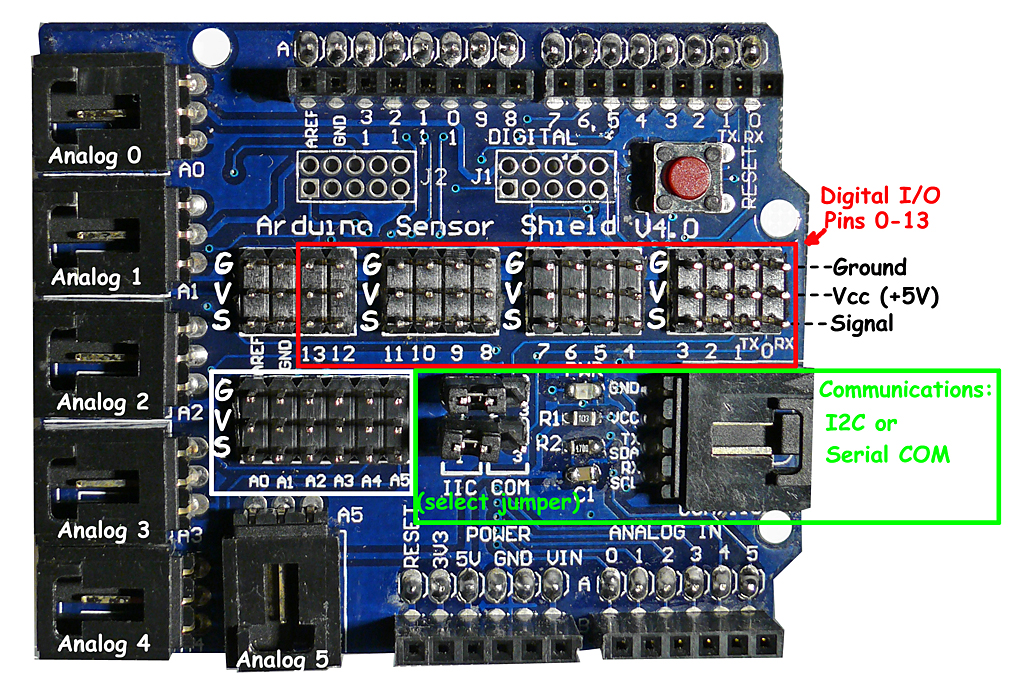
The Sensor Shield's purpose is make it easy to connect cables and devices to the correct Arduino pins. It is not an active device. It simply connects the Arduino pins to many connectors that are ready to use to connect to various devices like Servos and Sensors with simple cables. [/Cables (See more about CABLES here)]
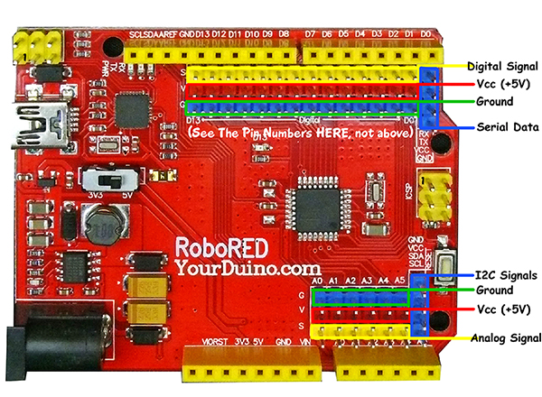
YourDuinoRoboRED: "Built-In Sensor Shield Connectors":
On the right is the YourDuinoRoboRED Arduino-compatible board. It has the 3-pin connectors similar to a Sensor Shield built-in.
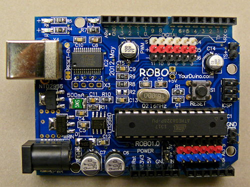
YourDuinoRobo1: "Built-In Sensor Shield Connectors":
Above is the YourDuinoRobo1 Arduino-compatible board. It has the 3-pin connectors similar to a Sensor Shield built-in. The top connector has 3 colors: Black=Gnd, Red=+5V, White=Signal. You will see that this matches the colors on the 3-pin cables. The bottom connector is for the Analog Inputs, and has Gnd - +5V - Signal in the other direction.
NOTE: Shown above is Sensor Shield Version 4 which is commonly used.
SENSOR SHIELD VERSION 5:
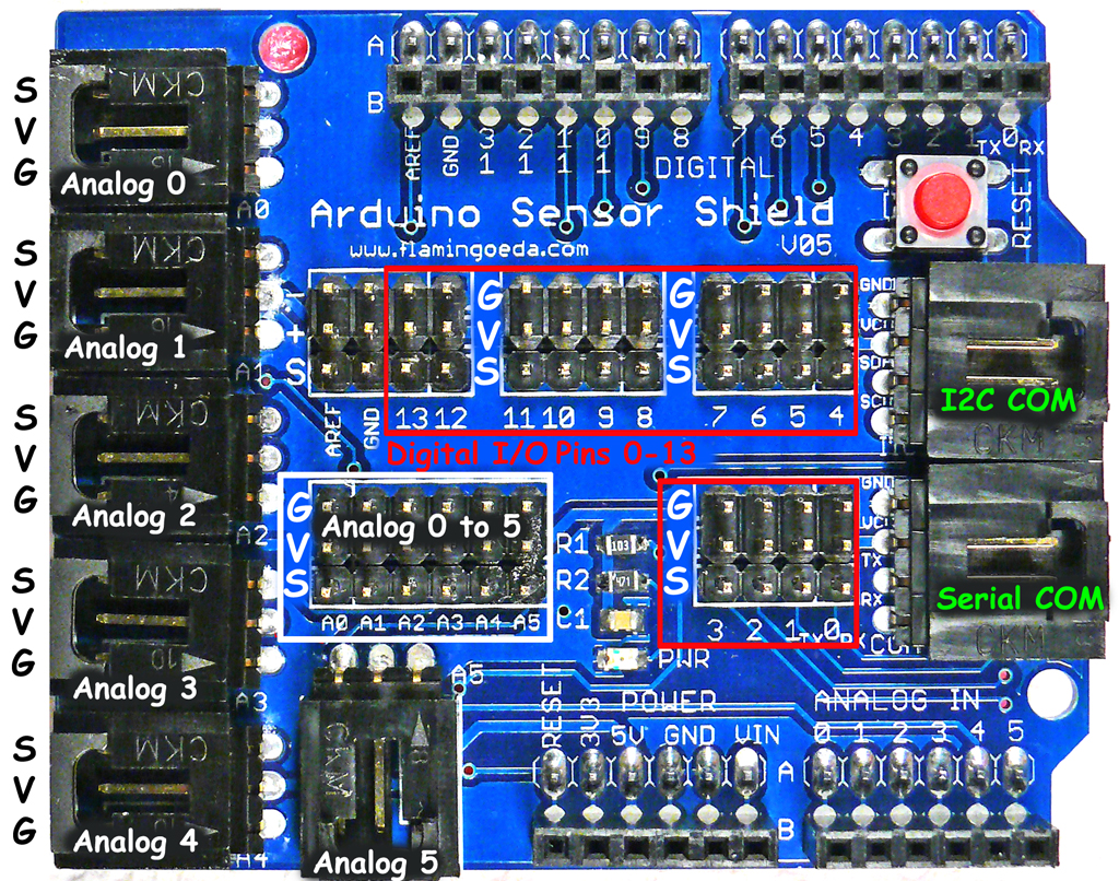
Below is Sensor Shield Version 5 , which is the same except 2 communications ports are provided to use Serial and I2C communications simultaneously.
NOTE: There is also a Sensor Shield for the Arduino MEGAwhich you can see here: and at the bottom of this page.
Each Port has 3 pins which are connected to (Ground), (Vcc + 5 V) and (Signal). See the GVS labels above. Cables normally are color coded so you know the right way to plug them in:
|
Ground |
Black |
|
Voltage |
Red |
|
Signal |
White or Yellow |
DIGITAL I/O PINS 0 to 13:
These are available in the rows outlined in red above. They connect with cables to Electronic Bricks and other INPUT DEVICES and OUTPUT DEVICES.
ANALOG INPUT PINS A0 to A5:
These are available in the row outlined in white above, AND on the black "Latched" connectors labeled "Analog 0" to "Analog 5". They also connect with cables to Electronic Bricks and other INPUT DEVICES.
COMMUNICATIONS PORT:
This connector can go to external Bricks or other devices that have more complex Communications Protocols to work with Arduino. Examples are GPS receivers, Ethernet interfaces, and other complex devices. These are 4-pin connectors.
Either SERIAL COMMUNICATIONS (COM) or "I squared C" (often written as I2C or IIC) are supported on V4. The two selectjumper blocks shown above are moved to select one or the other.
On V5 there are separate connectors for SERIAL and I2C Communications.
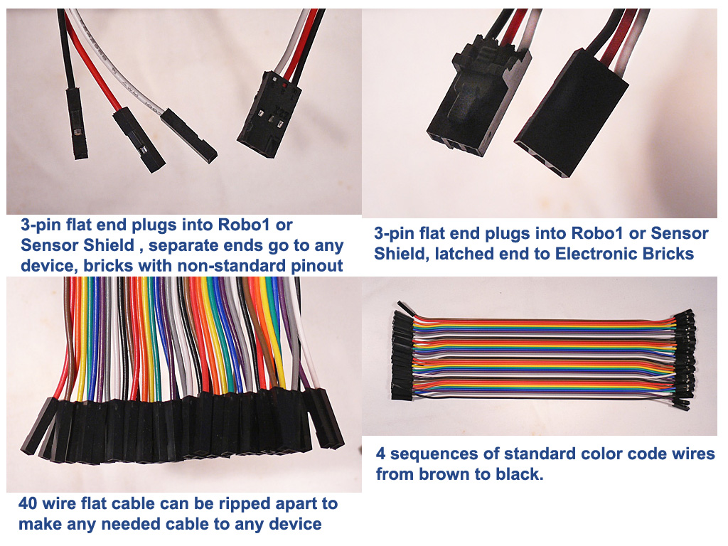
Other cables can connect, like these examples:
MEGA Sensor Shield
Find it HERE: MEGA SENSOR SHIELD
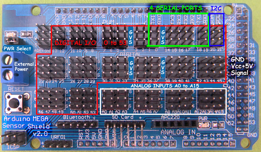
The Arduino MEGA has many more I/O pins (54 Digital pins and 16 Analog pins) than a standard Arduino. This shield also has connectors specifically for some external devices like an SD Card, Radio communications (Bluetooth and others). It also has an option to power the "V" pins on all the Digital I/O 3-pin groups from an external power supply instead of the Arduino +5V. This is good for large numbers of servos etc. The "Analog" 3-pin groups still use the Arduino +5V which is better from an electrical noise perspective.
This version has two options of +5V supply to all the "V" pins:
- Jumper on: +5 comes from the Arduino. Should be limited to about 300 ma
- Jumper off: +5 (or other appropriate voltage) comes from an external supply connected to the blue terminal strip. External power Ground must also be connected to the blue terminal strip.
Using an external supply allows more current than the Arduino or Mega can supply, such as current for control of many servos or relays, and other attached devices. Usually this is +5V because most external devices require it. It is possible to use +6 volts if ALL the attached devices are the same such as Servos with that rating.
Maximum CURRENT ratings:
The Yourduino Mega Sensor Shield V1.3 has been tested to find maximum allowable currents when external power is supplied on the Blue Terminal Block and the power jumper from the Mega is Removed. This is of special interest when a large number of Servos are driven from a Mega/Sensor Shield for Art / Automation / Animation installations. NOTE: In such applications it is helpful to limit the total/instantaneous Servo currents by staggering the start of several servo's moves a little,and possibly controlling their speed. The library "VarSpeedServo" may help See It Here
The Sensor Shield is a passive device made up of a Printed Circuit Board (PCB), solder-in PINS and a blue Terminal Block to supply external power. Typical "Wall Wart" external power supplies are 5V at 1 or 2 Amps, and there are modular supplies of 5V at 5 Amps which is probably the highest that should be used.
- Individual physical PIN current rating is maximum of 4 amps. Typically many pins will be used, each at a lower current.
- Blue Terminal Block is rated about 8 amps
- The Printed Circuit Board has internal and external copper layers that connect to the Ground pins, Voltage Pins and Signal Pins.
- The (S) Signal pins come from the Mega and should never exceed 40 milliamperes (0.04 amps) See Details Here
- The (G) Ground pins are connected to an internal copper layer and have a low resistance (0.02 to 0.07 ohms) to the Terminal Block GROUND connection
- The (V) Voltage pins are connected to an internal copper layer and have a low resistance (0.02 to 0.07 ohms) to the Terminal Block VOLTAGE connection.
- EXCEPT!! The Analog Input Pins A0 to A15 have a different Voltage plane that comes from the Arduino Mega 5V supply. Do not connect high current devices like Servos to these pins.
Dedicated Connectors (pins left to right, top to bottom, per above picture)
- ICSP: RST, D52/SCK, D50/MISO, GND, D51/MOSI, 5V
- Bluetooth: 3V3, GND, D0/RX0, D1/TX0, GND, 5V
- SD Card: D50/MISO, D52/SCK, D53/SS, D51/MOSI, 5V, GND
- APC220 (Wireless): --, D19/RX1, D18/TX1, --, 5V, GND
- URF01 (ultrasonic): 5V, D48, D49, GND
