Kufy-GEN-Project
DISCUSSION / LINKS
INFO about ESP32 HTTP Servers
Droneworkshop Shows web server controlling servo
Rui Santos webs server example for servo
Expressif The Expressif blog site MANY, Many links
Other Companies Info
Example: For Predator Inverter Type https://generatorupgradesupply.com/products/remote-start-and-stop-complete
VIDEO of Above: https://www.youtube.com/watch?v=qkvqGZPfkso
SMARTGEN (Chinese import on Ebay) https://www.ebay.com/itm/312582765000
Remote Start Generator Controllers https://www.ats4pro.com/collections/remote-start-generator-controllers https://www.ats4pro.com/collections/all https://www.ats4pro.com/collections/amf-controllers
Australian versions: https://mygenerator.com.au/media/Pramac-2-Wire-Auto-Start-Controller.pdf
ATKINSON ELECTRONICS, INC https://genconnexdirect.net/Liturature/Technotes/GSCM-mini_Datasheet.pdf
Circuit Diagrams
Many connection diagrams for many different gensets for a specific controller: https://www.magnum-dimensions.com/References/AutoGenStart
Generator Automatic Controls Project
Collecting thoughts, materials, designs for an automatic Generator Control for the Nigerian environment
TERRY: A LOT OF THIS MAY BE OBSOLETE!!
PARTS for generator controls
MEASUREMENT DEVICES
BATTERIES
LINKS:
https://www.google.com/search?lr=&as_qdr=all&ei=4cUnXfH_KOym_QbYqa-wCQ&q=best+deep+cycle+battery+in+nigeria&oq=best+deep+cycle+battery+in+nigeria https://jiji.ng/272-deep-cycle-batteries/12v
CHARGE Controllers
This is one I use on 3 systems here: Media:CamperPowerUnit-109821E_english_manual.pdf
TRANSFER RELAYS
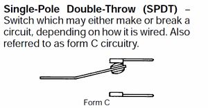
TRANSFER SWITCHES There are two considerations, but the FIRST one is critical: It needs to be virtually IMPOSSIBLE for the generator to "Feed Back" into the power line. If it did, there are BAD things that can happen: (1) DANGER to other people, especially Power Company workers, who thought the circuit was off. and (2) overload of the generator and possible damage due to not being synchronized with other power sources on this line. You need a relay system that CAN NOT connect the generator to the external power line, even if it has a fault. So the Solid State Relays "would be great" but they can fail, and thy usually fail 'shorted'... So you need a relay / contactor that is "Form C" which would also be called "Double Pole, Double Throw"..
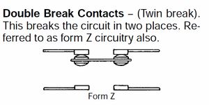
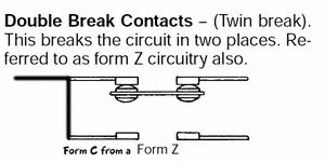
Relay Contact "Form"
Examples of possible Transfer Relays - LINKS:
(1) THIS is a 100 Amp rated relay with ONE "Form Z" contact. It would take TWO of these to create a "2C" or "Double pole double throw" relay.
//www.aliexpress.com/item/32888156121.html
NOTE: A relay with TWO "form Z" contacts would be good.
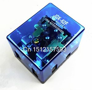
(2) THIS is a 80 Amp rated relay with two "Form Z" contacts. (Type JQX-62F-2Z ) This may be the best choice. This is equivalent to but better that a "Double Pole Double Throw".
//www.aliexpress.com/item/32805059192.html
(3) THIS is a 80 Amp rated relay with two "Form C" contacts. So it is "Double Pole Double Throw". It is physically for "DIN Rail Mount" so that's not necessary.
//www.aliexpress.com/item/477268399.html
Nigerian Power - Generators and Controls
Power in Home and businesses 230V 50 Hz. 1 Phase to smaller homes, 3 phase to businesses.
Typical home: 230V at ??? current??
https://www.huffingtonpost.com/timi-soleye/why-nigeria-generates-so-_b_5695091.html
https://en.wikipedia.org/wiki/Nigerian_energy_supply_crisis
THE DESIGN
NOTES:
VERSION/Editor: 1.05 TK
DATE/TIME: 15 Jul 2019 03:44 NT
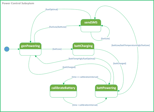
SOME BEGINNER STATE MACHINES?
CELL_POWER_MANAGER (highest level)
loop: {
CheckSensors // Update global variables
CheckCommunications // Receive new communications. Update display as needed, Send communications as needed
BatteryManager //Monitors Battery, SOC, decides if GeneratorPowerRequested is TRUE/FALSE
Generator_Engine_Manager // Maintains the STATE of the GEN. Starts, Stops, etc. Monitors GeneratorPowerRequested
(Check schedule?)
MakeDecisions // Based on overall system: Data Variables, STATES of other sub-managers
TakeActions // Set variables to new values, Change STATE of sub-managers
}
Battery_MANAGER
NOTE: Includes Charger status and control
Check_SOC // reads current Battery voltage, other parameters as available
CheckLoadStatus
if (SOC < Setpoint) // Needs both high and low SOC values
set Generator_Power_Requested TRUE
ELSE
set Generator_Power_Requested POWER FALSE
CheckBatteryHealth
(Do whatever)
GENERATOR/ENGINE MANAGER
STATES:
StoppedNormal
IF GeneratorPowerRequested set State to Starting
Starting //(Cranking, checking for sucess)
Start_Success
Start_Failure // Wait time, then change state to Starting. Too may attempts, set StartFailure
Running_Startup // Warmup
Running_Normal // Load is applied
IF GeneratorPowerRequested is FALSE, set State to StoppingNormal
Stopping Normal // Load disconnected, CoolDown
/*---( Fault States )------*/
Stopping_Low_Fuel // Send alarm
Stopped_LowFuel
Stopping_Electrical_Fault
Stopped_Electrical_Fault
GLOBAL DATA DEFINITIONS
(StateVariable for each State Machine)
Global Status variables like GeneratorPowerRequired
Current Fuel Level
PowerSourceStatus (Battery/Generator/Both)
GLOBAL CONSTANTS
Things for a specific installation, like:
Fuel Tank Capacity
Battery AH rating
Nominal Cell System power load
Fuel Level Low Alarm Setpoint
Battery Temperature High Alarm Setpoint
(Engine Parameters) - MaxCrankingSeconds - Start_Failure_Retry_Delay - Start_Attempts_allowed
Diagram examples
currently working on a more concise State Diagram
INFORMATION: KNOWN ENGINES AND GENSETS
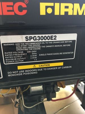
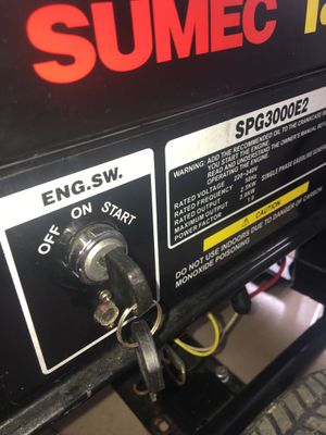
Kufy GENERATOR Manufacturer information
Manufacturer Name: SUMEC FIRMAN
Specifications
SERIAL NUMBER = SF200190095002151
USA Harbor Freight ENGINES
212CC 6.5 HP
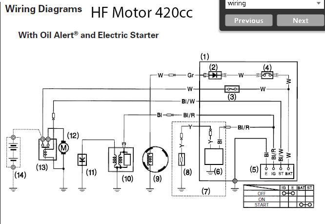
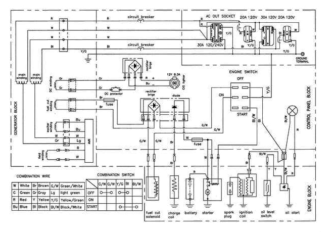
420cc 13.0 HP
Electrical Diagram
Anyone with better resolution scan PLEASE email terry@yourduino.com!
USA Harbor Freight GENSETS
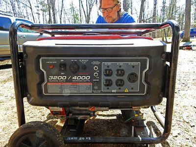
8750/7000W GenSet
Page with details of physical Gen wiring
Electrical Diagram
Anyone with better resolution scan PLEASE email terry@yourduino.com!
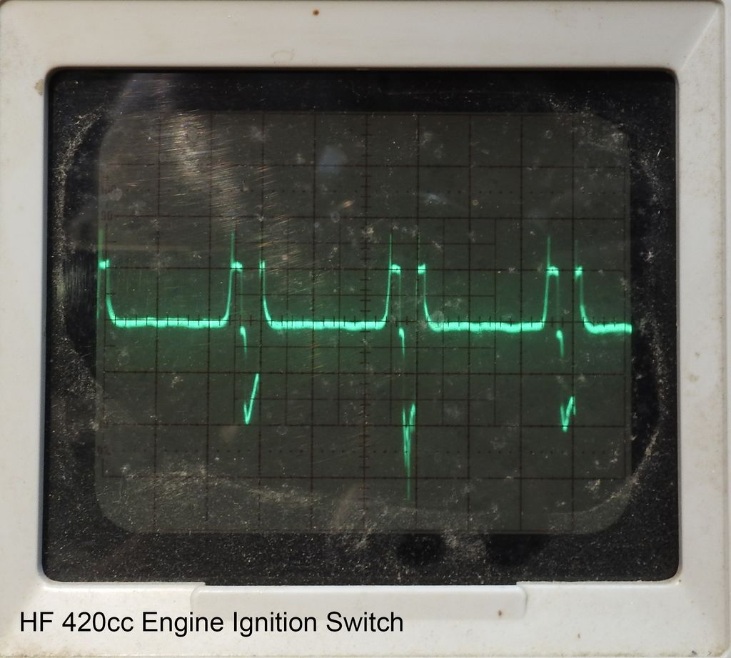
IGNITION WIRE WAVEFORM
This is at the ignition switch RUN-KILL
10V per Vertical division (10x probe), 5 ms per Horizontal division (Thanks, Barry)
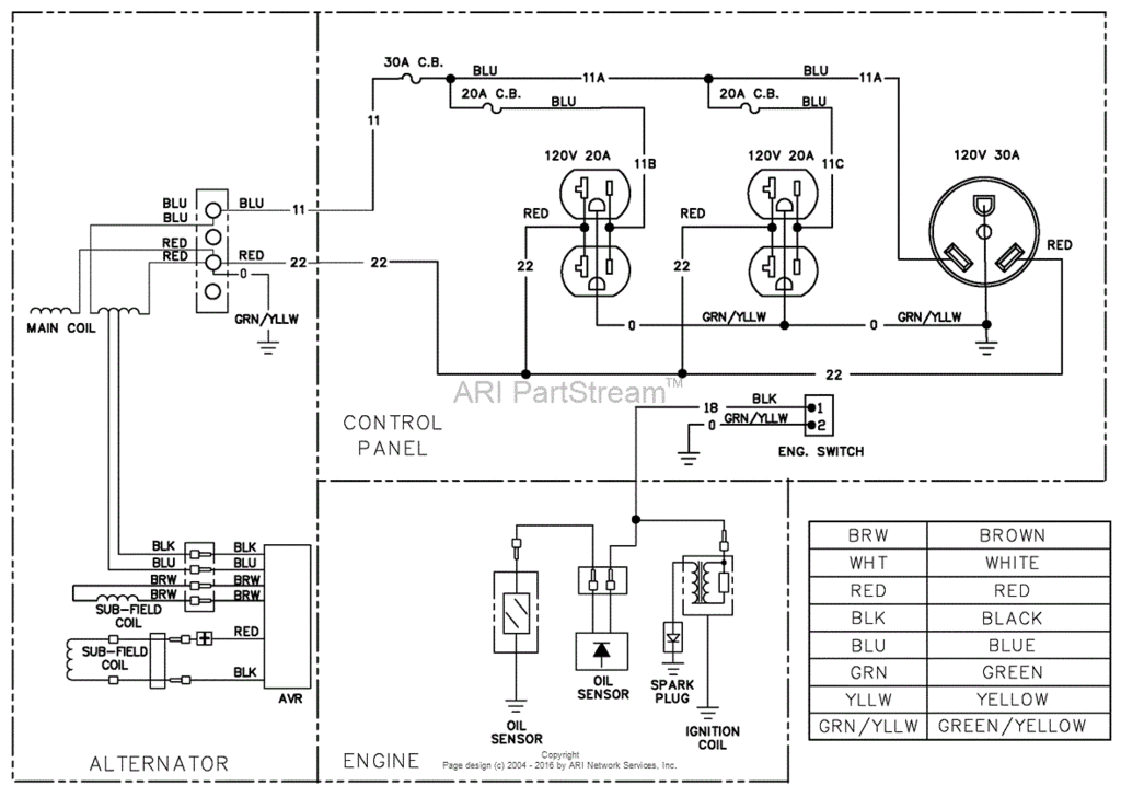
8750/7000W GenSet
Electrical Diagram (MIGHT be Right??
** Engine Alone (Not Gen) does not have low oil INDICATOR **
Anyone with better resolution scan PLEASE email terry@yourduino.com!
CONNECTORS-WIRING-CONNECTIONS
This is about how to make it easy to install our kit on a variety of Gens. We are starting on the two Harbor Freight Gens Barry and Terry have and the Firman that Kufy has.
These gens all will need new connections made to control Stop-Run-Start as a minimum. Most low-medium cost gens do not have any connector for remote control. So we must connect to them in a way that is minimally intrusive and can be done by semi-skilled installers or the customer. This means that our kit connections must be made either to:
- Existing removeable Tab type connectors OR
- Existing wires by adding new connections to them.
Most gens have .25 Inch wide "Tab" connectors that go to switches, sensors etc. That MAY be one solution.
Tab type connectors
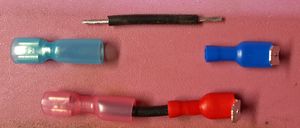
3-way: Create Tap: Example
These 'tab' connectors create a third connection point. They provide a male tab connection that can be used with a plain female tab connection as shown here. If assembled like this, they can go "In between" existing gen connections such as the male tab connections on switches etc.
If a female tab connector is connected to a male tab on a switch, for example, an added female connection is created. This is shown on the three terminals of the Stop-Run-Start switch on Terry's 8750W Harbor Freight gen:
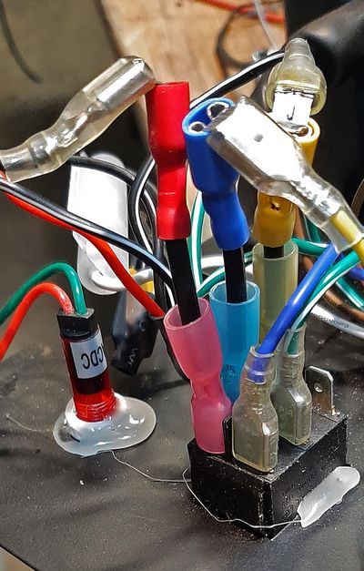
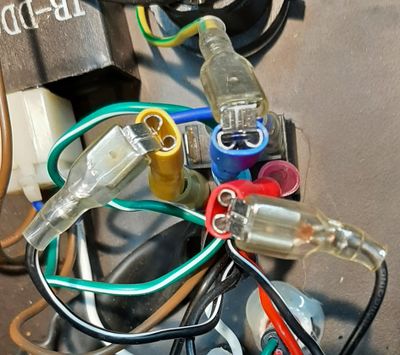
Each of the 3 connections now has an added female tab point where our kit cable (with a male tab) can connect.
PLUSSES AND MINUSES
PLUS:
- Can be completely removed
- reliable connections
- easy to test connections
MINUS:
- Needs access to inside of control panel: requires some disassembly
Clamp-on connectors that do "Insulation Displacement"
These connectors "clamp" on an existing wire without any cutting or disconnection of existing wiring. They usually clamp onto the middle of an existing wire and add one more wire from that circuit to go to our kit.
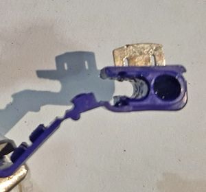
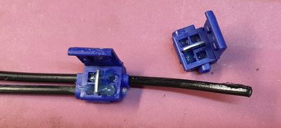
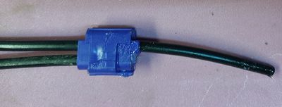
The basic connector looks like the individual piece on the left here. The through section on the left is wrapped around the existing wire without cutting it. The added "tap" wire goes into the dark hole on the right (That wire is also unstripped). Once in position the metal section is forced down over the two wires, making the connection, and the rest of the plastic jacket is clicked down like the third photo.
There is also an insulation-displacement connector that clamps on an existing wire and provides a female Tab connection. This may be useful when some wire needs to be CUT and connections made, AND reconnection may be needed if kit is removed. It looks like this (This is a better quality version):

PLUSSES:
- Easy and quick to connect
- Fairly secure and reliable connection (IF high quality part used) [We had some samples that were not good].
MINUSES:
- Not removeable: At least a short wire section with added tab connectors will be 'permanently' attached.
- If disconnection from the kits is required they must have an additional tab-connector pair on the end of the added wire. It should be female so it does not leave an uninsulated end flapping around if the kit cable is disconnected..
