StarterSet-GettingStarted
GETTING STARTED: YourDuino Starter Sets
Using the Arduino "IDE" software looks virtually the same on Windows, MAC or Linux, but the Installation procedures are different. Below, you can pick which one you need.
  Oh, "What's this IDE thing all about anyway" ?? The Arduino Integrated Development Environment
 (WikiPedia) is the one place you can do almost everything about Arduinos and Arduino software Development.
- [/ArduinoInstall-MAC MAC Installation]
- [/ArduinoInstall-WIN WINDOWS Installation]
- Linux Installation
After Installation, or if your board is already installed, continue here:
 CHECK OUT THE YourDuinoRobo1:

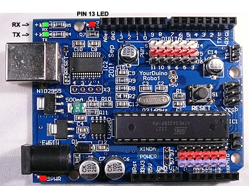
On the right, let's look at some of the features of the Robo1 board as used in many of the Starter Sets. At the lower left is the PWR LED which should light up whenever the board is plugged into a USB connection, or has power from an external power supply.
  At the upper left there are two green LEDs which will blink when a software sketch is being downloaded to the board, or other data is being transferred over USB.
  At the top is a red LED which is internally connected to pin 13 through a current-limiting resistor. It should blink after you load the example BLINK software sketch.
(FOR ALL OF US, NOW: MAC, WINDOWS, LINUX):
RUN THE ARDUINO "IDE" SOFTWARE:
OK, so you've got your YourDuino plugged in and running. The POWER"ON" LED is on, right? And the "13" LED is blinking? (This may be a little different for the various Arduino clones, and the '13' LED may or may not blink now).
IT'S SOFTWARE TIME:
Let's take a little while to get used to writing Arduino Software, then we'll come back and start connecting your Starter kit parts and making more interesting things.

  On your desktop you should now have the Arduino ICON like this:
|
|
| external image Arduino-Icon1-68.jpg |

 Click on it, if you haven't already, and you should see the "Arduino IDE Window" pop up like this:

  You'll use this IDE (Integrated Development Environment) to make Software VISIBLE! Here you will develop your own software to make Arduino into what you want it to be.

SKETCHES:
The visible text of an Arduino software program is called a SKETCH. But the Sketch becomes alive when you upload it to your Arduino. Let's walk through looking at a Sketch and Verifying it and Uploading it:

 Click on FILE and then move your mouse (slowly.. It's Fussy!) over EXAMPLES and BASICS and BLINK
  so it looks like this (On the right):

 And CLICK. There are lots of examples that come with the free Arduino software system, and we will look at some of them later, as well as make our own very soon.

  A new IDE window should pop up and look like this:

  Wow.. A bunch of new stuff.

  Let's slow down and "Watch Closely Now"!

  Notice that a lot of the text is GREY. All of that is just "Comments" for you to read to help understand the Sketch. When you write software, you should also use "Comments" to explain to others what you are doing. (Arduino itself totally ignores these comments).

  Now, let's go through changing software, Verifying it, and Uploading it to see Arduino DO it. We'll use the BLINK example for now, but in a while you'll start with a totally blank page and write your own programs.

  Every Arduino Program has the same basic structure:


- SETUP - Runs Once at the beginning
- LOOP - Runs over and over again, forever
You will read a LOT of program "Code" that other people wrote, in the future. You HAVE to "Watch Closely Now" and really see the details. Read the example through carefully, a couple of times. Note the colored special words that are Instructions. These are unique words that tell Arduino what to do. They have to be spelled perfectly!
What SETUP does: Instructs Arduino about things that need to be done once. Remember that Arduino Digital Pins can be either INPUT or OUTPUT. You have to tell Arduino when a Pin will be used as an OUTPUT. In this example, there is one line that tells Arduino that Pin 13 must be an OUTPUT.
external image Arduino-IDA-Pinmode1.jpg
Note the COLOR of the lettering. The Arduino IDE changes the color of words as it recognizes them as special instructions. Let's mess with them:
pinMode: Note that when Instructions are two words run together, like pinMode, the beginning of the SECOND word is Capitalized. Mess with it: Change the Capital "M" to "m". Note the color changes to black. Hmmm. Click the VERIFY ![]() button.
button.
You will get an ERROR message: ![]()
Fussy, Fussy, Fussy! Yep, every letter has to be correct and also correct upper or lower case.
Change it back. Check the color. Click Verify again. OK??
What does VERIFY do??![]()
A LOT! More details later, but Verify is a program in your main computer that goes through every Instruction in your Sketch (Ignoring "Comments") and checks it against the list of valid Instructions, and checks that the structure and sequence of the statements in the Sketch are correct. Fussy, Fussy! If that's OK, then it "compiles" or "translates" the sketch into the actual machine code that Arduino actually runs on. It saves that 'ready-to-run' code for you to Upload to Arduino and run. Other systems would call this process "Make" or "Compile".
What does UPLOAD do??![]()
First, Upload runs Verify to check and compile your program. Then it communicates to your Arduino over the USB connection, resets the Arduino chip, and talks to software already on Arduino (called the BOOTLOADER(W)) to load your new program into the Arduino's memory. Then it restarts Arduino and your program runs it's SETUP section and then repeats the LOOP section.
Start Making Changes:
Ok, let's make a few changes to the sample BLINK program:

The LOOP section of your program does all the instructions in the section, and then "loops" back to the top and starts it again, over and over.
NOTE: the "Brackets" { and }
Notice that the beginning and end of the section is "inside brackets". You will see many sections of bigger programs that are grouped by these "brackets".
Now, let's look in detail at the instructions:
Instruction: digitalWrite
This instruction sets an OUTPUT PIN to either HIGH (connects it to +5 V) or LOW (Connects it to GND). Remember: HIGH = 1 = ON = 5V
So, the first line in LOOP sets PIN 13 to HIGH. There is an LED and resistor already connected to PIN 13, so the LED lights up.
Instruction: delay
The delay instruction just waits for a period of time. The VALUE used with delay is in Milliseconds (1/1000 second). So delay(1000); waits for 1000/1000 seconds (1 second). We'll change that soon.
NOTE: the ";"
Notice that every instruction is followed by the character " ; " which is like a period that tells the end of the sentence.
Change the delay so that the LED blinks differently:
Time to mess about and try some things! Maybe we'll break it. Then we'll fix it..
Suggestion: Save your own version of BLINK so you can always go back to the original one. Go to File and Save As and call it something like MyBlink. This will go in your SKETCHBOOK where you'll save your own programs.
Now go change the VALUE in a delay statement to change the way the LED blinks. Think about the the 4 instructions in LOOP. What's happening??
Turn the LED on. Wait and look at the LED.
Turn the LED off. Wait and look at the dark.
So, let's change the ON time to be short. Maybe 50 Milliseconds. That's 1/20 of a second. Then try 10 milliseconds. The LED is only on 1/100 of the time. Can you still see it blink? How about 1 millisecond?
Each time you make a change, click Upload![]() which will first Verify and Compile your program and then send it to Arduino. Notice that each time you do this the LEDS that are marked "Tx" (Transmit) and "Rx" (receive) flash as your main computer communicates with your Arduino.
which will first Verify and Compile your program and then send it to Arduino. Notice that each time you do this the LEDS that are marked "Tx" (Transmit) and "Rx" (receive) flash as your main computer communicates with your Arduino.
Try some combinations of ON and OFF times. Like ON 1000 and OFF 50.
Try making both ON and OFF times shorter and shorter. If you make the ON and OFF times short enough your eye will no longer see blinking, because of "Persistence of Vision"(W) which happens when there are more than about 25 blinks per second. So, hmmm.... if you make the LED be ON for 1/50 of a second and OFF for 1/50 of a second that should do it. So try 1000/50= 20 Milliseconds. Put 20 for both the ON and OFF times. What do you see?? How about 10 Milliseconds each? Depending on your personal eye's physiology, at some speed you will not see any more blinks.
All right. You're the Programmer! You can save any of the sketches for use later on. Go to File>Sketchbook and you'll see them.
Next, we'll start hooking Electronics Parts! There are two types of Starter Sets. One uses Electronic Bricks and 3-pin cables to plug many different Input Devices and Output Devices into a Robo1 or a Sensor Shield. The other uses a Breadboard and cables and jumper wires to connect to the different devices.
Here is a How-To for the Breadboard based Low Cost Starter Sets: [/LowCostStarterSet-Connecting-Breadboarding (GO THERE)]
Here is a How-To for the Electronic Brick Starter Set: [/StarterSet-Circuits-Pins-Bits (GO THERE)]