Analog-Output
Analog-Output: How-To
Credits: http://www.makingthings.com/documentation
Sometimes you need Arduino to output a true "Analog Output" which is a voltage that can be set at values from (usually) 0.0 to 5.0 volts. But the Arduino "analogWrite()" instruction (See the Reference page here) does not put out a true Analog signal, but rather one that pulses back and forth between 0 and 5 volts rapidly. The percentage of the time it is ON vs Off allows it to be used successfully to dim LEDs, control motors speed, etc. But WhatIf you need "True Analog"??
Introduction to PWM and how to convert to true analog
Most integrated circuit based microcontrollers have digital outputs which are capable of outputting only 2 values, ON and OFF, or 100% and 0%. In other words, these act like a normal light switch, you can either flip the switch on or off, but there are no available intermediate values. There is no way to dim the lights with a typical light switch. However, many times we would like to control a voltage analogically using a microcontroller. Microcontrollers use a technique called 'Pulse Width Modulation' to simulate an analog voltage by rapidly switching between ON and OFF. PWM signals are similar to analog DC signals, but in truth they are still a form of AC signal. While acceptable in most appications, sometimes it is desirable to have true analog voltage control. Without additional components, however, this is not possible when using a microcontroller.
PWM
PWM switching is done at a frequency too high to be discerned by the human eye. It is helpful to think of this type of signal as a waveform. The idea is to continue toggling the output at a constant frequency, and during each period, the amount of time spent in the ON position can be varied. The percentage of time spent in the ON position is called the 'Duty Cycle'. Duty Cycle represents the width of a pulse. For a normal wave, like a sine wave, the duty cycle is 50%. The wave spends 50% of its time in the ON position and 50% in the OFF position. Over the period of the waveform, the average on-time is 50%, and if we continue this duty cycle, it will appear over time that the signal is 'half ON'. By varying this Duty Cycle, it appears to the human eye (and most devices) to be an intermediate value. In the chart below, several duty cycles are shown.

If we consider the light switch example above, we could theoretically simulate a dimmer switch when only a normal flip switch is available. If one were physically capable of toggling the light switch fast enough, the overall light intensity would be proportional to the time spent in the ON position, or the Duty Cycle. If we increase the time spent in the ON position, the brightness of the bulb will increase proportionally. If we spend 99% of the period in the ON position, the light will be 99% bright, and vice versa.
PWM is a technique used to create pseudo-analog signals. These signals appear to the human senses to be analog, but closer inspection shows that these signals are not truly analog. For most hobby projects, PWM is totally acceptable, and is an excellent option for most applications.
Creating a True Analog Signal
While a PWM signal may be acceptable in many situations, it is often necessary to use a true analog signal. This may be the case for high speed electronics, or other sensitive loads. In order to create an analog signal, it is necessary to modify the PWM signal described above.
A PWM signal can be smoothed using a filter. This smoothing effect will translate the signal into the 'average' output voltage of the PWM. A low pass filter as shown below is the correct type to use for this application.
A Practical Circuit from Nick Gammon:
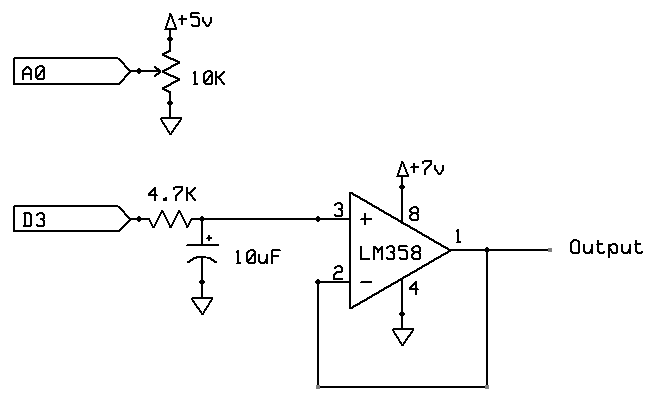
How it Works>
Capacitors effectively resist voltage change. They attempt to maintain a stable voltage across their leads by accepting and dispensing electrons. During the ON cycle, the capacitor is filled up with electrons. As current flows through the resistor and fills up the capacitor, voltage is dropped over the resistor. This voltage drop is proportional to the current to the capacitor, and therefore is also related to the depletion of the capacitor. Thus, the overall voltage seen at the output will be lower than the PWM. At this time, the system is preparing for the OFF cycle. During the OFF cycle of the PWM, the capacitor releases its surplus of electrons and attempts to maintain the voltage that was established during the ON cycle.
Signal processing tells us that all waveforms can be broken down into sinusoidal components. Even audio signals like music can be broken down into a sum of thousands of unique sinusoidal waves of varying frequency and amplitude. In square waves, such as those present in PWM signals, most of these components are high frequency sinusoids of low voltage. The purpose of any filter is to cut out unwanted frequency components. As we are using a Low Pass Filter, high frequency voltage changes are cut out, leading to smoother waves. As such, effective capacitor and resistor combinations will depend greatly on the frequency (not Duty Cycle) of the input PWM signal. Care should be taken to select the appropriate values based on this frequency.
"Time Constant" and "Time to reach final Value"
The "Time Constant" (for the voltage to reach 63% of final value) is R * C so .0047 seconds (4.7mS) in this case, for 4.7K and 1 uF (MICRO Farad) . (4700 * .000001)
In 10 T (time constants) the value will have reached 99% of it's final value. Thats .047 S in this case.
If you're not going to try to follow faster changes, maybe use 10 uF for .47S to "well-settled"..
But you have to decide how fast the analog value must be "Followed"....
Considerations
As the Low Pass Filter uses a capacitor on the output lead, funcitonality may be affected when connecting a system with nonlinear loading (one that includes inductive or capacitive loads). In other words, it may be advisable in some situations to pass this analog signal through some type of buffer that will negate any nonlinear loading effects. These effects would almost certainly affect the signal you have created with the filter. Care should be taken when designing circuits with nonlinear loading, although many times these loads can be fed directly with the controller and will filter the signal themselves. For this reason, most microcontrollers do not contain onboard filters.