BlueTooth-HC05-HC06-Modules-How-To
BlueTooth-HC05-Modules-How-To
Bluetooth [WikiPedia] is a wireless technology standard for exchanging data over short distances (using short-wavelength UHF radio waves in the ISM band from 2.4 to 2.485 GHz) from fixed and mobile devices, and building personal area networks (PANs). Range is approximately 10 Meters (30 feet).
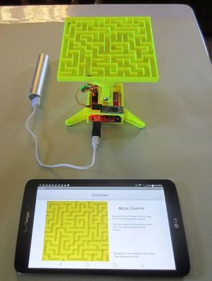
HERE's a great Instructable: CLICK HERE that shows how to make a Android phone control a 3-D maze(Photo on right) through this HC05 module, a YourDuino RoboRED and a couple of servos. (And some 3-D printed parts!)

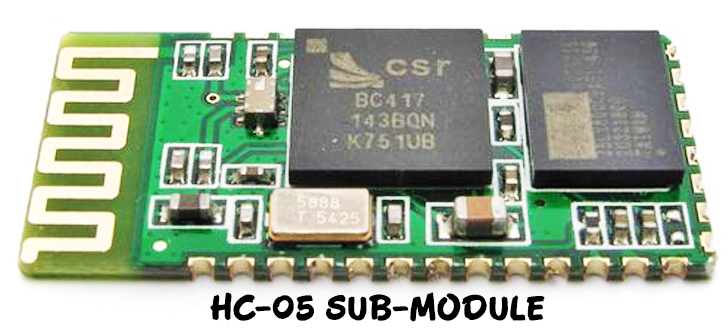
These modules are based on the Cambridge Silicon Radio BC417 2.4 GHz BlueTooth Radio chip. This is a complex chip which uses an external 8 Mbit flash memory. If you like LOTS of details see the: [Data Sheet]. These low-cost Bluetooth Sub-modules work well with Arduino and other Microcomputers. IMPORTANT Definitions:
- HC-05 is a more capable module that can be set to be either Master or Slave (Available HERE)
- HC-06 is a Slave only device. (It looks physically just like the HC-05).(Note: Now HC-06 not cheaper)
- These small ( 3 cm long) modules run on 3.3V power with 3.3V signal levels, They have no pins and usually solder to a larger board. (See example below)
- The module has two modes of operation, Command Mode where we can send AT commands to it and Data Mode where it transmits and receives data to another bluetooth module.
- "Breakout" Boards that make these easy to use are available and recommended. These mount the sub-module like that shown on the right on a slightly larger board. NOTE: Sellers often label them "HC-05" or "HC-06", but they have some other model number on the reverse side. Most of these boards support operation at 5V power and interface to 5V Arduino signal levels with some technique of level shifting. A typical "breakout" board is shown below:
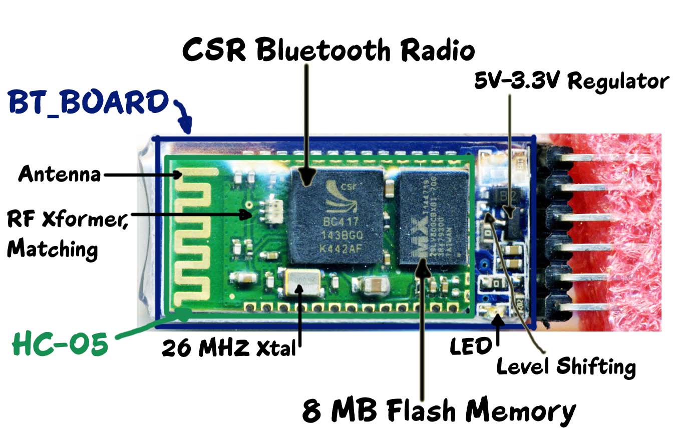
The Keyes / YourDuino BT Board

(Available HERE) Sections of the BT Board (Above):
- The Green HC-05 sub-module is soldered on top of the Blue BT Board
- The HC-05 module includes the Radio and Memory chips, 26 MHz crystal, antenna and RF matching network.
- The right section of the BT Board has connection pins for power and signals as well as a 5V to 3.3V Regulator, LED, and level shifting.
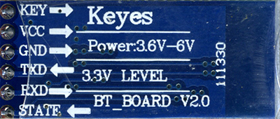
HC-05 PinOut (Right) :
- KEY: If brought HIGH before power is applied, forces AT Command Setup Mode. LED blinks slowly (2 seconds)
- VCC: +5 Power
- GND: System / Arduino Ground
- TXD: Transmit Serial Data from HC-05 to Arduino Serial Receive. NOTE: 3.3V HIGH level: OK for Arduino
- RXD: Receive Serial Data from Arduino Serial Transmit
- STATE: Tells if connected or not
BlueToothCommandUtility:
(LINK) Arduino Sketch to send and receive Command Mode AT commands to HC-05 to change configuration.
COMMAND and DATA TRANSFER MODES:
The module has two modes of operation, Command Mode where we can send AT commands to it and Data Mode where it transmits and receives data to another bluetooth module. The default mode is DATA Mode, and this is the default configuration, that may work fine for many applications:
- Baud Rate: 9600 bps, Data : 8 bits, Stop Bits: 1 bit, Parity : None, Handshake: None
- Passkey: 1234
- Device Name: HC-05
In some cases you may want to change some of the configuration setup values. There are two ways to get into Command Mode:
- Connect the KEY pin high before applying power to the module. This will put the module into command mode at 38400 baud. This is commonly used, and needed if you don't know the baud rate the module is set to. You can use the BlueToothCommandUtility (LINK) for this.
- Apply power to the module then pull the KEY pin high. This will enter command mode at the currently configured baud rate. This is useful if you want to send AT commands from a microcontroller as the KEY pin can be controlled from one of the microcontroller pins. BUT you need to know the currently configured Baud Rate.
Commands are sent to the module in UPPERCASE and are terminated with a CR/LF pair.
Command Mode Commands:
The format of commands is:
- Always starts with "AT"
- Then "+" followed by <ParameterName>
- Then either:
- ? (returns current value of parameter)
- = (New Value of parameter)
A few examples:
- AT (AT Test command. Should respond with OK)
- AT+VERSION? (show the firmware version)
- AT+UART=9600,0,0 (Set baud rate to 9600, 1 stop bit, no parity)
Bluetooth Master Mode:
To configure the module as Bluetooth Master and to pair with another bluetooth module follow these steps. First we need to put the module into command mode as above by pulling the CMD pin high before power on. (Use the BlueToothCommandUtility (LINK) for this.)Enter these commands in order:
- AT+RMAAD Clear any paired devices
- AT+ROLE=1 Set mode to Master
- AT+RESET After changing role, reset is required
- AT+CMODE=0 Allow connection to any address (I have been told this is wrong and CMODE=1 sets "any address"
- AT+INQM=0,5,5 Inquire mode - Standard, stop after 5 devices found or after 5 seconds
- AT+PSWD=1234 Set PIN. Should be same as slave device
- AT+INIT Start Serial Port Profile (SPP) ( If Error(17) returned - ignore as profile already loaded)
- AT+INQ Start searching for devices
A list of devices found will be displayed, one of which is the slave module. The format of the output is +INQ:address,type,signal The address of the module is what we need and is in the format 0123:4:567890NOTE: We need to replace the colons with commas when we use the address with the following commands. If you get more than one device listed and don't know which one is the slave module, you can query the module for it's name using: AT+RNAME? <address> e.g. (don't forget to change the colons to commas) AT+RNAME? 0123,4,567890 Once we are happy we have the correct slave address, we need to pair with it, so carry on with the next set of commands:
- AT+PAIR=<address>,<timeout> The timeout is in seconds and if you need to type in the pin on the slave device you need to give enough time to do this.
- AT+BIND=<address> Set bind address to the slave address
- AT+CMODE=0 (Correction!) Allow master to ONLY connect to bound address (slave). This allows the master to automatically connect to the slave when switched on
- AT+LINK=<address> Connect to slave.
Slave Mode:
The HC-05 bluetooth module can also act as a slave. There are fewer commands to set this up:
- AT+ORGL Reset to defaults
- AT+RMAAD Clear any paired devices
- AT+ROLE=0 Set mode to SLAVE
- AT+ADDR Display SLAVE address
LINKS to MORE INFORMATION:
http://elasticsheep.com/2011/05/serial-bluetooth-module-masterslave-connection/ A good explanation..

