Brick-Temperature-DS18B20
Temperature Sensor DS18B20
(See Thermocouples for high temperatures HERE)

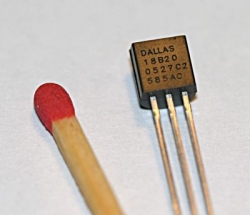
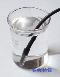
Electronic Brick, Waterproof and other Versions
NOTE: There are different-appearing versions of the DS18B20 electronic temperature sensor but they work the same. This is an electronic thermometer which has high accuracy over a wide range (accurate to ±0.5°C over the range of -10°C to +85°C) (Workable from -55°C to +125°C).
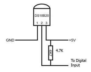
You can locate these thermometer chips up to 100M away from your Arduino. Shorter cables can be just 2 wires. NOTE: There must be a pullup resistor of about 5K in all cases, but the Brick versions have this included.
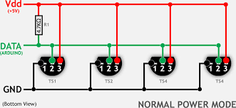
Multiple thermometers can be connected on the same wire because every one has it's own internal address. This is the "1-wire" bus system(Wikipedia). Below is an example of connecting up to 5 DS18B20's on a single Arduino pin. This requires that you know the internal address of each sensor. A utility sketch to find the address is also below.
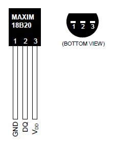
Here (above, right) is what the individual chip sensors look like, and their pinout (below):
Links to more about the DS18B20 and other "1-Wire" chips
NOTE: See the table of contents on the DS18B20 Page
- TEST PROGRAM: single DS18B20 Temperature Sensor]
- Example that displays multiple DS18B20 temperatures on a 4-line LCD Display
- The DS18B20 Data Sheet
- Download The updated "DallasTemperature" Library (zip file)
- Download The updated "1-Wire" Library (zip file) (Probably not needed any more)
- "1-Wire" information
- The Software Library and information from Miles Burton
- * https://arduinoinfo.mywikis.net/wiki/Brick-Temperature-DS18B20#Multiple_DS18B20_Example: HOW-TO Connect several DS18B20 on same wires> ]
- https://arduinoinfo.mywikis.net/wiki/Brick-Temperature-DS18B20#Read_individual_DS18B20_Internal_Addresses: Read individual DS18B20 Internal Addresses:]
- http://arduinoinfo.mywikis.net/wiki/Brick-Temperature-DS18B20#Test%20Sketch%20to%20read%20DS18B20%20addresses Test Sketch to read DS18B20 addresses]
- http://arduinoinfo.mywikis.net/wiki/Brick-Temperature-DS18B20#multibus Multiple 1-Wire Buses on 1 Arduino]
- MAXIM Application note about Long Cables
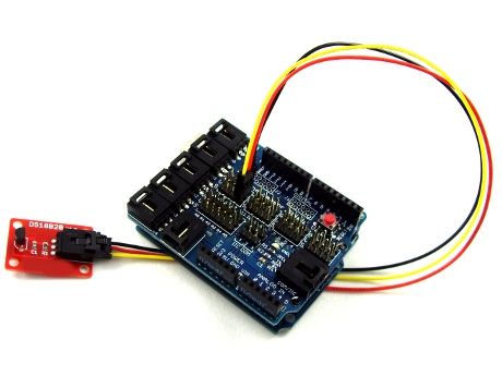 The DS18B20 Brick is the easiest way to get connected and measure temperatures. Or a waterproofed version
The easy way to get connected is to simply plug the supplied cable into a YourDuinoRoboRED with built-in 3-pin connectors.
How does this Work??
Now, let's think for a minute about what we're doing here. The earlier devices we connected were simple: Switches, LEDs, Potentiometers, etc. A single component. This is different: we are connecting to a chip that has hundreds of transistors inside it and dozens of possible functions. It expects us to send it commands and it will return data as lots of signal pulses of 1's and 0's. How will we communicate with it? Fortunately, we're not in an empty room. We're in a library.
On the shelves, free for us to check out, are lots of already-published Arduino functions that we can use. We will use two library check-outs to run our temperature sensor that other people have spent 100's of hours working on, and given us unlimited copies to check out. (Terry's wife designs Libraries.Here's one she designed in China: Luckily for us, now she is writing more Arduino HOW-TO!)
To make this work, you MUST download and install the library DallasTemperature chips and copy it to your Arduino software installation Library folder. (See above).
(each one is called a "Library" not a Book! )
For more about Libraries see our Arduino Libraries page.
Then just copy and paste this test code (below) into your http://arduinoinfo.mywikis.net/wiki/GettingStarted-Software Arduino IDE]:
NOTE: If using the YourDuinoRobo1, connect to pin 3 (and change the pin number in the code below to 3).
Then:
 Click the VERIFY button. Soon you should see "Compiling" and "Done Compiling"
 Click the UPLOAD button. You should see "Uploading to IO Board" and "Done Uploading"
 Now, click the SERIAL MONITOR button. (Make sure you have the baud rate set to 9600 baud in lower right of Serial Monitor). A new window should pop up and scroll lines of results showing you.. Temperature!
Troubleshooting?? Go back and get the original BLINK program working first. http://arduinoinfo.mywikis.net/wiki/GettingStarted-Software Check Here:]
Sketch to test DS18B20
/* YourDu05/21/2018
- Connect cable to Arduino Digital I/O Pin 2

***  FIX Wire.h include
terry@yourduino.com */


/*-----( Import needed libraries )-----*/
//#include <OneWire.h>    // Included within recent DallasTemperature
#include <DallasTemperature.h>

/*-----( Declare Constants )-----*/
#define ONE_WIRE_BUS 2 /*-(Connect to Pin 2 )-*/

/*-----( Declare objects )-----*/
/* Set up a oneWire instance to communicate with any OneWire device*/
OneWire ourWire(ONE_WIRE_BUS);

/* Tell Dallas Temperature Library to use oneWire Library */
DallasTemperature sensors(&ourWire);

/*-----( Declare Variables )-----*/


void setup() /*----( SETUP: RUNS ONCE )----*/
{
/*-(start serial port to see results )-*/
delay(1000);
Serial.begin(9600);
Serial.println("YourDuino.com: Temperature Sensor Test Program");
Serial.println("Temperature Sensor: DS18B20");
delay(1000);

/*-( Start up the DallasTemperature library )-*/
sensors.begin();
}/*--(end setup )---*/


void loop() /*----( LOOP: RUNS CONSTANTLY )----*/
{
Serial.println();
Serial.print("Requesting temperature...");
sensors.requestTemperatures(); // Send the command to get temperatures
Serial.println("DONE");

Serial.print("Device 1 (index 0) = ");
Serial.print(sensors.getTempCByIndex(0));
Serial.println(" Degrees C");
Serial.print("Device 1 (index 0) = ");
Serial.print(sensors.getTempFByIndex(0));
Serial.println(" Degrees F");
delay(5000);
}/* --(end main loop )-- */

/* ( THE END ) */
What You Should See (Your temperature may vary! Hold the sensor in your hand and see value increase):
YourDuino.com: Temperature Sensor Test Program
Temperature Sensor: DS18B20

Requesting temperature...DONE
Device 1 (index 0) = 25.12 Degrees C
Device 1 (index 0) = 77.22 Degrees F
If you see THIS there is a connection or sensor problem!
YourDuino.com: Temperature Sensor Test Program
Temperature Sensor: DS18B20

Requesting temperature...DONE
Device 1 (index 0) = -127.00 Degrees C
Device 1 (index 0) = -196.60 Degrees F
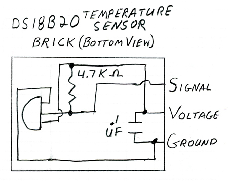
Here's the schematic diagram of the Brick:
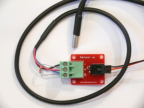
And here is another form of exactly the same DS18B20 temperature sensor in a waterproof stainless steel tube. These are Available Here).
You have the same connections to voltage and ground and signal, but you have to provide your own 4.7K "pullup" resistor which can be any small type resistor (two 10K resistors in parallel works well). Be careful to ensure the Signal and Ground connections are correct. If they are reversed, the sensor can get quite hot (even at such a low voltage).
Here (above) is a photo of this sensor connected to a [1] "3-pin Sensor" connector]so that it can be connected like our regular Electronic Bricks. You can see the 4.7K pullup resistor connected between + and Signal.
Sensor Connections: red (VCC), blue or white or yellow (DATA), black (GND)
Some Versions, like Adafruit, have these connections: Orange Stripe: (VCC) White: (GND) Blue Stripe:(DATA)
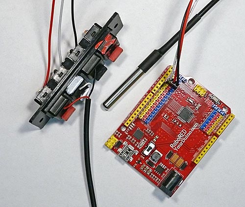
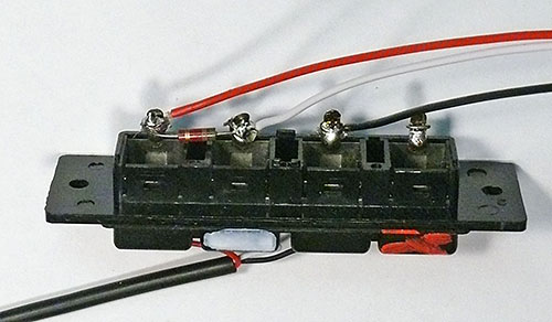
And on the right is a handy connection method if you need to quickly connect many temperature sensors to get their addresses, like I do. That's one of those Stereo speaker connectors that you push the
button in and push the wire in place. Scavenged from an old Stereo. Notice the resistor (4.7K to 10K OK) on the back from +5 (Red) to Signal (White).
Read Temperatures from multiple DS18B20 sensors on 1 Arduino Pin:
You will need to know the internal address of each sensor. Farther below is a Utility Sketch that can read the address from sensors one at a time. You need to cut and paste the addresses, first to a text file and later into the example multi-sensor example sketch below.
Multiple DS18B20 Example:
NOTE: For an example that displays multiple DS18B20 temperatures on a 2-line OR 4-line LCD Display SEE THIS EXAMPLE:
/* YourDuino Multiple DS18B20 Temperature Sensors on 1 wire
  Connections:
  DS18B20 Pinout (Left to Right, pins down, flat side toward you)
  - Left   = Ground
  - Center = Signal (Pin 2):  (with 3.3K to 4.7K resistor to +5 or 3.3 )
  - Right  = +5 or +3.3 V

   Questions: terry@yourduino.com
   V1.01  01/17/2013 ...based on examples from Rik Kretzinger

/*-----( Import needed libraries )-----*/
// Get 1-wire Library here: http://www.pjrc.com/teensy/td_libs_OneWire.html
#include <OneWire.h>

//Get DallasTemperature Library here:  http://milesburton.com/Main_Page?title=Dallas_Temperature_Control_Library
#include <DallasTemperature.h>

/*-----( Declare Constants and Pin Numbers )-----*/
#define ONE_WIRE_BUS_PIN 2

/*-----( Declare objects )-----*/
// Setup a oneWire instance to communicate with any OneWire devices
OneWire oneWire(ONE_WIRE_BUS_PIN);

// Pass our oneWire reference to Dallas Temperature.
DallasTemperature sensors(&oneWire);

/*-----( Declare Variables )-----*/
// Assign the addresses of your 1-Wire temp sensors.
// See the tutorial on how to obtain these addresses:
// http://www.hacktronics.com/Tutorials/arduino-1-wire-address-finder.html

DeviceAddress Probe01 = { 0x28, 0x8A, 0xB1, 0x40, 0x04, 0x00, 0x00, 0xC7 };
DeviceAddress Probe02 = { 0x28, 0xCC, 0x92, 0x40, 0x04, 0x00, 0x00, 0xB6 };
DeviceAddress Probe03 = { 0x28, 0x4D, 0x8D, 0x40, 0x04, 0x00, 0x00, 0x78 };
DeviceAddress Probe04 = { 0x28, 0x9A, 0x80, 0x40, 0x04, 0x00, 0x00, 0xD5 };
DeviceAddress Probe05 = { 0x28, 0xE1, 0xC7, 0x40, 0x04, 0x00, 0x00, 0x0D };


void setup()   /****** SETUP: RUNS ONCE ******/
{
  // start serial port to show results
  Serial.begin(9600);
  Serial.print("Initializing Temperature Control Library Version ");
  Serial.println(DALLASTEMPLIBVERSION);

  // Initialize the Temperature measurement library
  sensors.begin();

  // set the resolution to 10 bit (Can be 9 to 12 bits .. lower is faster)
  sensors.setResolution(Probe01, 10);
  sensors.setResolution(Probe02, 10);
  sensors.setResolution(Probe03, 10);
  sensors.setResolution(Probe04, 10);
  sensors.setResolution(Probe05, 10);

}//--(end setup )---

void loop()   /****** LOOP: RUNS CONSTANTLY ******/
{
  delay(1000);
  Serial.println();
  Serial.print("Number of Devices found on bus = ");
  Serial.println(sensors.getDeviceCount());
  Serial.print("Getting temperatures... ");
  Serial.println();

  // Command all devices on bus to read temperature
  sensors.requestTemperatures();

  Serial.print("Probe 01 temperature is:   ");
  printTemperature(Probe01);
  Serial.println();

  Serial.print("Probe 02 temperature is:   ");
  printTemperature(Probe02);
  Serial.println();

  Serial.print("Probe 03 temperature is:   ");
  printTemperature(Probe03);
  Serial.println();

  Serial.print("Probe 04 temperature is:   ");
  printTemperature(Probe04);
  Serial.println();

  Serial.print("Probe 05 temperature is:   ");
  printTemperature(Probe05);
  Serial.println();


}//--(end main loop )---

/*-----( Declare User-written Functions )-----*/
void printTemperature(DeviceAddress deviceAddress)
{

float tempC = sensors.getTempC(deviceAddress);

   if (tempC == -127.00)
   {
   Serial.print("Error getting temperature  ");
   }
   else
   {
   Serial.print("C: ");
   Serial.print(tempC);
   Serial.print(" F: ");
   Serial.print(DallasTemperature::toFahrenheit(tempC));
   }
}// End printTemperature
//*********( THE END )***********
Read individual DS18B20 Internal Addresses:
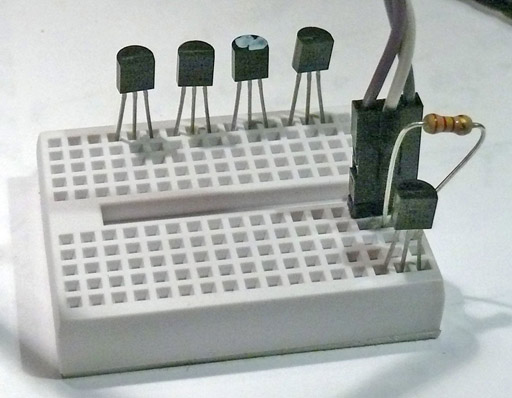
Here's a way to connect multiple DS18B20's to get their addresses and test them: A 3-wire cable connects Arduino +5V, Ground and Pin 2 to a small breadboard. The breadboard can "Store" DS18B20's you are working on, and 1 or more can be connected for test.
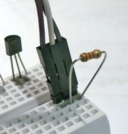
Here's a closeup of the connections: Left=Ground, Center=Data, Right=+5V, 3300 to 4700 ohm resistor from +5V to Data.
Find your sensors and put them in the top "Storage" row of the breadboard. Then put them one at a time in the active 3 columns on the lower right. You will use the Software Sketch below to get the individual addresses.
Next, cut and paste the sketch below into an Arduino IDE blank window. Save it. Upload it. Then open the Serial Monitor window. You should see this:
Found '1-Wire' device with address:
0x28, 0x8A, 0xB1, 0x40, 0x04, 0x00, 0x00, 0xC7
Done
That address is unique to that DS18B20.. not another the same anywhere! Open a text file and cut/paste the address to save it. I'd label it Sensor1 and put that sensor back in the first "storage" position. Do the same for the rest of your sensors. The sensors are hard to physically mark. "Sharpie" Paint Markers can work. Or an electric engraver works OK. Tape?
Now cut/paste the "Multiple DS18B20 Example" Sketch above. Save. Edit it to put the addresses of your sensors in the lines that look like this:
DeviceAddress Probe01 = { 0x28, 0x8A, 0xB1, 0x40, 0x04, 0x00, 0x00, 0xC7 };
Save, Upload. Plug your first DS18B20 in. Then open the Serial Monitor window. You should see this:
Getting temperatures...
  Probe 01 temperature is: C: 26.75 F: 80.15
  Probe 02 temperature is: Error getting temperature
  Probe 03 temperature is: Error getting temperature
  Probe 04 temperature is: Error getting temperature
  Probe 05 temperature is: Error getting temperature
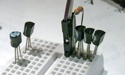
Now try plugging in 2 or 3 sensors at once, like this:
Now more sensors should show temperature readings. Wait about 5 minutes for them to stabilize and they should all be within 0.5 Degrees C.
Test Sketch to read DS18B20 addresses:
(Cut and paste from Serial Monitor)
/* YourDuino Example: Find Address of a DS18B20 Temperature Sensor
 Cut and paste the address to a text file for later use.
 V1.1 01/17/2013
 Questions: terry@yourduino.com

 Connections:
 DS18B20 Pinout (Left to Right, pins down, flat side toward you)
 - Left   = Ground
 - Center = Signal (Pin 2):  (with 3.3K to 4.7K resistor to +5 or 3.3 )
 - Right  = +5 or +3.3 V
 This sketch looks for 1-wire devices and  prints their addresses (serial number)
 to the Serial Monitor in a format that is useful in Arduino sketches.
 Based on example at:
 http://www.hacktronics.com/Tutorials/arduino-1-wire-address-finder.html
 */

/*-----( Import needed libraries )-----*/
#include <OneWire.h>

/*-----( Declare Constants and Pin Numbers )-----*/
#define SENSOR_PIN 2  // Any pin 2 to 12 (not 13) and A0 to A5

/*-----( Declare objects )-----*/
OneWire  ourBus(SENSOR_PIN);  // Create a 1-wire object

void setup()  /****** SETUP: RUNS ONCE ******/
{
  Serial.begin(9600);

  discoverOneWireDevices();  // Everything happens here!
}//--(end setup )---

void loop()   /****** LOOP: RUNS CONSTANTLY ******/
{
  // Nothing happening here
}

/*-----( Declare User-written Functions )-----*/
void discoverOneWireDevices(void) {
  byte i;
  byte present = 0;
  byte data[12];
  byte addr[8];

  Serial.print("Looking for 1-Wire devices...\n\r");// "\n\r" is NewLine
  while(ourBus.search(addr)) {
    Serial.print("\n\r\n\rFound \'1-Wire\' device with address:\n\r");
    for( i = 0; i < 8; i++) {
      Serial.print("0x");
      if (addr[i] < 16) {
        Serial.print('0');
      }
      Serial.print(addr[i], HEX);
      if (i < 7) {
        Serial.print(", ");
      }
    }
    if ( OneWire::crc8( addr, 7) != addr[7]) {
      Serial.print("CRC is not valid!\n\r");
      return;
    }
  }
  Serial.println();
  Serial.print("Done");
  ourBus.reset_search();
  return;
}

//*********( THE END )***********
MULTIPLE 1_WIRE BUSES:
It is possible to have multiple 1-wire buses as well as multiple DS18B20's on each bus. Here is a test Sketch that creates two buses and searches each bus for 1-wire devices:
/* YourDuino Example: Find Address of a DS18B20 Temperature Sensor
 Search two electrically separate busses.
 Cut and paste the address to a text file for later use.
 V1.0 01/18/2013
 Questions: terry@yourduino.com

 Connections:
 DS18B20 Pinout (Left to Right, pins down, flat side toward you)
 - Left   = Ground
 - Center = Signal (Pin 2):  (with 3.3K to 4.7K resistor to +5 or 3.3 )
 - Right  = +5 or +3.3 V
 This sketch looks for 1-wire devices and  prints their addresses (serial number)
 to the Serial Monitor in a format that is useful in Arduino sketches.
 Based on example at:
 http://www.hacktronics.com/Tutorials/arduino-1-wire-address-finder.html
 */

/*-----( Import needed libraries )-----*/
#include <OneWire.h>

/*-----( Declare Constants and Pin Numbers )-----*/
#define SENSOR_1_PIN 2 // For BUS 1
#define SENSOR_2_PIN 4 // For BUS 2

/*-----( Declare objects )-----*/
OneWire  Bus1(SENSOR_1_PIN);  // Create a 1-wire object
OneWire  Bus2(SENSOR_2_PIN);  // Create another 1-wire object

void setup()  /****** SETUP: RUNS ONCE ******/
{
  Serial.begin(9600);
  Serial.println("Searching for DS18B20's on two different busses");
  Serial.println();

  Serial.println("Searching for DS18B20's on BUS ONE");
  discoverBusOneWireDevices();

  Serial.println();
  Serial.println();

  Serial.println("Searching for DS18B20's on BUS TWO");
  discoverBusTwoWireDevices();
}//--(end setup )---

void loop()   /****** LOOP: RUNS CONSTANTLY ******/
{
  // Nothing happening here
}

/*-----( Declare User-written Functions )-----*/

void discoverBusOneWireDevices(void)
{
  byte i;
  byte present = 0;
  byte data[12];
  byte addr[8];

  Serial.print("Looking for 1-Wire devices...\n\r");// "\n\r" is NewLine
  while(Bus1.search(addr)) {
    Serial.print("\n\rFound \'1-Wire\' device with address:\n\r");
    for( i = 0; i < 8; i++) {
      Serial.print("0x");
      if (addr[i] < 16) {
        Serial.print('0');
      }
      Serial.print(addr[i], HEX);
      if (i < 7) {
        Serial.print(", ");
      }
    }
    if ( OneWire::crc8( addr, 7) != addr[7]) {
      Serial.print("CRC is not valid!\n\r");
      return;
    }
  }
  Serial.println();
  Serial.print("Done");
  Bus1.reset_search();
  return;
}// END

//------------------------------------------------------------
void discoverBusTwoWireDevices(void)
{
  byte i;
  byte present = 0;
  byte data[12];
  byte addr[8];

  Serial.print("Looking for 1-Wire devices...\n\r");// "\n\r" is NewLine
  while(Bus2.search(addr)) {
    Serial.print("\n\rFound \'1-Wire\' device with address:\n\r");
    for( i = 0; i < 8; i++) {
      Serial.print("0x");
      if (addr[i] < 16) {
        Serial.print('0');
      }
      Serial.print(addr[i], HEX);
      if (i < 7) {
        Serial.print(", ");
      }
    }
    if ( OneWire::crc8( addr, 7) != addr[7]) {
      Serial.print("CRC is not valid!\n\r");
      return;
    }
  }
  Serial.println();
  Serial.print("Done");
  Bus2.reset_search();
  return;
}//END


//*********( THE END )***********
DS18B20 CLONES and COUNTERFEITS
These chips are so popular that 3 or 4 other companies have made their own versions.. And SOME chips are made to LOOK like the Dallas/Maxim original. Those would be Counterfeits not just Clones.
There is a LOT of information about this on This GITHUB Site . You can download some test sketches there. Here is one that works well at showing all the internal differences.
  1 /*
  2  * Copyright Chris Petrich
  3  *
  4  * Licensed under the Apache License, Version 2.0 (the "License");
  5  * you may not use this file except in compliance with the License.
  6  * You may obtain a copy of the License at
  7  *
  8  *     http://www.apache.org/licenses/LICENSE-2.0
  9  *
 10  * Unless required by applicable law or agreed to in writing, software
 11  * distributed under the License is distributed on an "AS IS" BASIS,
 12  * WITHOUT WARRANTIES OR CONDITIONS OF ANY KIND, either express or implied.
 13  * See the License for the specific language governing permissions and
 14  * limitations under the License.
 15  *
 16  *   File:    discover_fake_DS18B20.ino
 17  *   Author:  Chris Petrich
 18  *   Version: 22 Oct 2019
 19  *
 20  *   Source:  https://github.com/cpetrich/counterfeit_DS18B20/
 21  *   Documentation:  https://github.com/cpetrich/counterfeit_DS18B20/
 22  *
 23  * This demonstration script performs authenticity tests on DS18B20 sensors by
 24  * evaluating ROM code and Scratchpad Register. It uses documented ROM commands
 25  * F0h and 55h and Function Commands 44h, 4Eh and BEh, only.
 26  * It does not test the power-up state and it does not write to or test the EEPROM.
 27  * It is INTENDED for EDUCATIONAL PURPOSES, only.
 28  * There may be circumstances under which the sketch permanently damages one-wire
 29  * sensors in obvious or non-obvious ways.
 30  * (I don't think it does that to authentic Maxim sensors, but I won't guarantee
 31  * anything. See licence text for details.)
 32  *
 33  *
 34  * This script is written for Arduino. Wiring:
 35  *
 36  * CPU Vcc         -------o------ DS18B20 Vcc
 37  *                        |
 38  *                       [R]  <- choose resistor appropriate for supply voltage and current that the microcontroller is able to sink.
 39  *                        |
 40  * CPU pin_onewire -------o------ DS18B20 data
 41  *
 42  * CPU GND         -------------- DS18B20 GND
 43  *
 44  */
 45
 46 // Tested with OneWire Version 2.3
 47 // https://github.com/PaulStoffregen/OneWire
 48 #include "OneWire.h"
 49
 50
 51 #define pin_onewire 8
 52 #define pin_LED 13
 53
 54 #define Comm Serial
 55
 56
 57 OneWire *ds;
 58
 59 void print_hex(uint8_t value) {
 60   if (value < 16) Comm.write('0');
 61   Comm.print(value, HEX);
 62 }
 63
 64 void print_array(uint8_t *data, int n, char sep = ',') {
 65   int idx;
 66   for (idx=0; idx<n; idx++) {
 67     print_hex(data[idx]);
 68     if (idx != n-1)
 69       Comm.write(sep);
 70   }
 71 }
 72
 73 bool read_scratchpad(uint8_t *addr, uint8_t *buff9) {
 74   ds->reset();
 75   ds->select(addr);
 76   ds->write(0xBE); // read scratchpad
 77   int idx;
 78   for (idx=0; idx<9; idx++)
 79     buff9[idx] = ds->read();
 80   return 0 == OneWire::crc8(buff9, 9);
 81 }
 82
 83 void setup() {
 84   Comm.begin(115200);
 85   Comm.println();
 86
 87   digitalWrite(pin_LED, HIGH);
 88   pinMode(pin_LED, OUTPUT);
 89
 90   ds = new OneWire(pin_onewire);
 91
 92   {
 93     // output file name without leading path
 94     char *file = __FILE__;
 95     int i;
 96     for (i = strlen(file); i > 0; i--)
 97       if ((file[i] == '\\') || (file[i] == '/')) {
 98         i++;
 99         break;
100       }
101     Comm.print(F("\n--- # "));
102     Comm.println(&file[i]);
103   }
104   digitalWrite(pin_LED, LOW);
105   Comm.println(F("This sketch will test DS18B20 sensors attached to"));
106   Comm.print(F("  pin "));
107   Comm.print(pin_onewire, DEC);
108   Comm.println(F(" for differences with Maxim Integrated-produced DS18B20"));
109   Comm.println(F("  using only functionality documented in the datasheet and in"));
110   Comm.println(F("  Maxim Application Note AN4377."));
111   Comm.println();
112 }
113
114 void loop() {
115   // ROM address of current sensor
116   uint8_t addr[8];
117   // buffers for scratchpad register
118   uint8_t buffer0[9];
119   uint8_t buffer1[9];
120   uint8_t buffer2[9];
121   uint8_t buffer3[9];
122   // flag to indicate if validation
123   //  should be repeated at a different
124   //  sensor temperature
125   bool t_ok;
126
127   ds->reset_search();
128   while (ds->search(addr)) {
129     int fake_flags = 0;
130
131     print_array(addr, 8, '-');
132     if (0 != OneWire::crc8(addr, 8)) {
133       // some fake sensors can have their ROM overwritten with
134       // arbitrary nonsense, so we don't expect anything good
135       // if the ROM doesn't check out
136       fake_flags += 1;
137       Comm.print(F(" (CRC Error -> Error.)"));
138     }
139
140     if ((addr[6] != 0) || (addr[5] != 0) || (addr[0] != 0x28)) {
141       fake_flags += 1;
142       Comm.print(F(": ROM does not follow expected pattern 28-xx-xx-xx-xx-00-00-crc. Error."));
143     } else {
144       Comm.print(F(": ROM ok."));
145     }
146     Comm.println();
147
148     if (!read_scratchpad(addr, buffer0)) read_scratchpad(addr, buffer0);
149
150     Comm.print(F("  Scratchpad Register: "));
151     print_array(buffer0, 9, '/');
152     if (0 != OneWire::crc8(buffer0, 9)) {
153       // Unlikely that a sensor will mess up the CRC of the scratchpad.
154       // --> Assume we're dealing with a bad connection rather than a bad
155       //     sensor, dump data, and move on to next sensor.
156       Comm.println(F("  CRC Error. Check connections or replace sensor."));
157       continue;
158     }
159     Comm.println();
160
161     // Check content of user EEPROM. Since the EEPROM may have been programmed by the user earlier
162     // we do not use this as a test. Rather, we dump this as info.
163     Comm.print(F("  Info only: Scratchpad bytes 2,3,4 ("));
164     print_array(buffer0+2,3,'/');
165     Comm.print(F("): "));
166     if ((buffer0[2] != 0x4b) || (buffer0[3] != 0x46) || (buffer0[4] != 0x7f))
167       Comm.println(F(" not Maxim default values 4B/46/7F."));
168     else
169       Comm.println(F(" Maxim default values."));
170
171
172     Comm.print(F("  Scratchpad byte 5 (0x"));
173     print_hex(buffer0[5]);
174     Comm.print(F("): "));
175     if (buffer0[5] != 0xff) {
176       fake_flags += 1;
177       Comm.println(F(" should have been 0xFF according to datasheet. Error."));
178     } else {
179       Comm.println(F(" ok."));
180     }
181
182     Comm.print(F("  Scratchpad byte 6 (0x"));
183     print_hex(buffer0[6]);
184     Comm.print(F("): "));
185     if ( ((buffer0[6] == 0x00) || (buffer0[6] > 0x10)) || // totall wrong value
186          ( ((buffer0[0] != 0x50) || (buffer0[1] != 0x05)) && ((buffer0[0] != 0xff) || (buffer0[1] != 0x07)) && // check for valid conversion...
187            (((buffer0[0] + buffer0[6]) & 0x0f) != 0x00) ) ) { //...before assessing DS18S20 compatibility.
188       fake_flags += 1;
189       Comm.println(" unexpected value. Error.");
190     } else
191       Comm.println(" ok.");
192
193     Comm.print(F("  Scratchpad byte 7 (0x"));
194     print_hex(buffer0[7]);
195     Comm.print(F("): "));
196     if (buffer0[7] != 0x10) {
197       fake_flags += 1;
198       Comm.println(F(" should have been 0x10 according to datasheet. Error."));
199     } else {
200       Comm.println(F(" ok."));
201     }
202
203     // set the resolution to 10 bit and modify alarm registers
204     ds->reset();
205     ds->select(addr);
206     ds->write(0x4E); // write scratchpad. MUST be followed by 3 bytes as per datasheet.
207     ds->write(buffer0[2] ^ 0xff);
208     ds->write(buffer0[3] ^ 0xff);
209     ds->write(0x3F);
210     ds->reset();
211
212     if (!read_scratchpad(addr, buffer1)) read_scratchpad(addr, buffer1);
213
214     Comm.print(F("  0x4E modifies alarm registers: "));
215     if ((buffer1[2] != (buffer0[2] ^ 0xff)) || (buffer1[3] != (buffer0[3] ^ 0xff))) {
216       fake_flags += 1;
217       Comm.print(F(" cannot modify content as expected (want: "));
218       print_hex(buffer0[2] ^ 0xff);
219       Comm.write('/');
220       print_hex(buffer0[3] ^ 0xff);
221       Comm.print(F(", got: "));
222       print_array(buffer1+2, 2, '/');
223       Comm.println(F("). Error."));
224     } else
225       Comm.println(F(" ok."));
226
227     Comm.print(F("  0x4E accepts 10 bit resolution: "));
228     if (buffer1[4] != 0x3f) {
229       fake_flags += 1;
230       Comm.print(F(" rejected (want: 0x3F, got: "));
231       print_hex(buffer1[4]);
232       Comm.println(F("). Error."));
233     } else
234       Comm.println(F(" ok."));
235
236     Comm.print(F("  0x4E preserves reserved bytes: "));
237     if ((buffer1[5] != buffer0[5]) || (buffer1[6] != buffer0[6]) || (buffer1[7] != buffer0[7])) {
238       fake_flags += 1;
239       Comm.print(F(" no, got: "));
240       print_array(buffer1+5, 3, '/');
241       Comm.println(F(". Error."));
242     } else
243       Comm.println(F(" ok."));
244
245     // set the resolution to 12 bit
246     ds->reset();
247     ds->select(addr);
248     ds->write(0x4E); // write scratchpad. MUST be followed by 3 bytes as per datasheet.
249     ds->write(buffer0[2]);
250     ds->write(buffer0[3]);
251     ds->write(0x7f);
252     ds->reset();
253
254     if (!read_scratchpad(addr, buffer2)) read_scratchpad(addr, buffer2);
255
256     Comm.print(F("  0x4E accepts 12 bit resolution: "));
257     if (buffer2[4] != 0x7f) {
258       fake_flags += 1;
259       Comm.print(F(" rejected (expected: 0x7F, got: "));
260       print_hex(buffer2[4]);
261       Comm.println(F("). Error."));
262     } else
263       Comm.println(F(" ok."));
264
265     Comm.print(F("  0x4E preserves reserved bytes: "));
266     if ((buffer2[5] != buffer1[5]) || (buffer2[6] != buffer1[6]) || (buffer2[7] != buffer1[7])) {
267       fake_flags += 1;
268       Comm.print(F(" no, got: "));
269       print_array(buffer2+5, 3, '/');
270       Comm.println(F(". Error."));
271     } else
272       Comm.println(F(" ok."));
273
274     Comm.print("  Checking byte 6 upon temperature change: ");
275     if (( ((buffer2[0] == 0x50) && (buffer2[1] == 0x05)) || ((buffer2[0] == 0xff) && (buffer2[1] == 0x07)) ||
276          ((buffer2[6] == 0x0c) && (((buffer2[0] + buffer2[6]) & 0x0f) == 0x00)) ) &&
277          ((buffer2[6] >= 0x00) && (buffer2[6] <= 0x10)) ){
278       // byte 6 checked out as correct in the initial test but the test ambiguous.
279       //   we need to check if byte 6 is consistent after temperature conversion
280
281       // We'll do a few temperature conversions in a row.
282       // Usually, the temperature rises slightly if we do back-to-back
283       //   conversions.
284       int count = 5;
285       do {
286         count -- ;
287         if (count < 0)
288           break;
289         // perform temperature conversion
290         ds->reset();
291         ds->select(addr);
292         ds->write(0x44);
293         delay(750);
294
295         if (!read_scratchpad(addr, buffer3)) read_scratchpad(addr, buffer3);
296
297       } while ( ((buffer3[0] == 0x50) && (buffer3[1] == 0x05)) || ((buffer3[0] == 0xff) && (buffer3[1] == 0x07)) ||
298                 ((buffer3[6] == 0x0c) && (((buffer3[0] + buffer3[6]) & 0x0f) == 0x00)) );
299       if (count < 0) {
300         Comm.println(F(" Inconclusive. Please change sensor temperature and repeat."));
301         t_ok = false;
302       } else {
303         t_ok = true;
304         if ((buffer3[6] != 0x0c) && (((buffer3[0] + buffer3[6]) & 0x0f) == 0x00)) {
305           Comm.println(F(" ok."));
306         } else {
307           fake_flags += 1;
308           Comm.print(F(" Temperature LSB = 0x"));
309           print_hex(buffer3[0]);
310           Comm.print(F(" but byte 6 = 0x"));
311           print_hex(buffer3[6]);
312           Comm.println(F(". Error."));
313         }
314       }
315     } else {
316       Comm.println(F("not necessary. Skipped."));
317       t_ok = true;
318     }
319
320     Comm.print(F("  --> "));
321     if (!t_ok) {
322       Comm.print(F("DS18S20 counterfeit test not completed, otherwise sensor"));
323     } else
324       Comm.print(F("Sensor"));
325
326     if (fake_flags == 0) {
327       Comm.println(F(" responded like a genuie Maxim."));
328       Comm.println(F("      Not tested: EEPROM, Parasite Power, and undocumented commands."));
329     } else {
330       Comm.print(F(" appears to be counterfeit based on "));
331       Comm.print(fake_flags, DEC);
332       Comm.println(F(" deviations."));
333       if (fake_flags == 1) {
334         Comm.println(F("  The number of deviations is unexpectedly small."));
335         Comm.println(F("  Please see https://github.com/cpetrich/counterfeit_DS18B20/"));
336         Comm.println(F("  to help interpret the result."));
337       }
338     }
339     Comm.println();
340   } // done with all sensors
341   Comm.println(F("------------------------------------------------"));
342   delay(4000);
343   digitalWrite(pin_LED, digitalRead(pin_LED) == HIGH ? LOW : HIGH);
344 }
LONG CABLES:
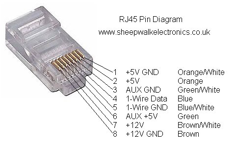
See the example above about Multiple DS18B20's. Most people use readily-available CAT5 Ethernet cable. There are no definite "Standards" for pinout of the cable but here is one that is often used. It also provides separate 5V and 12V power for remote devices:
TROUBLESHOOTING: parasite power
The way that the library detects parasite power is to issue a "Read Power Supply" command to the one-wire bus, to which parasite powered sensors will respond by pulling the bus low and non-parasite sensors will leave the bus as it is. So if any one, or more, of multiple sensors pull the bus low, the library assumes that ALL the sensors are parasite powered. If you have all sensors connected to +5V power then none of the sensors should be pulling the bus low, so if you see "Parasite Power" there's a wiring or other problem with the way that the sensors are connected.
zz
