DC-Motors
DC Motors
(Written, Composed and Illustrated by Mike Cook) Thanks!
Introduction
Small DC motors can take little current but they normally can’t be driven directly from the output pin of an Arduino or any other microcomputer chip . Therefore they need some sort of driver or current boost before you can control them. Also motors are a great source of interference that can make the rest of your electronics misbehave. This can be countered by isolating the motor power supply to a greater or lesser extent.
Basic Driving
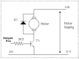
A motor will often need a higher voltage as well as higher current than can be supplied directly so an external power supply is normally used to provide this. The simplest way of driving a motor is directly through a transistor, as shown here:-
An output pin from the Arduino is connected through a resistor to the base of a transistor, the motor sits between the collector and the positive external power supply and the emitter is connected to ground, earth or zero volts (to give the line just three commonly interchangeable names). Note that the ground has to be common (connected together) between your external supply and the Arduino. A motor is basically an electromagnet or coil; in electronic terms this is an inductor. When you suddenly remove turn off the power, the magnetic field collapses because there is no current flowing to keep it up. This collapsing field then produces a “back EMF” or reverse voltage that can be several hundred volts. This has the potential to damage the electronics connected to the rest of the circuit and so it is normal practice to place a diode across the motor, in order to short this back-EMF out and protect you other components. This is most important and any sort of rectifier diode will do, like the popular 1N4004 or similar. The value of the base resistor is something that troubles some beginners, however, it is not too critical. It has to limit the base current, but not so much that the transistor doesn't turn on fully. Basically the base current times the "transistor current gain" has to equal or exceed the current taken by the motor. However, if the
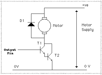
motor current is high your transistor will have to have a high collector current rating and some transistors of this type don’t have a very high gain. If that is the case you can use this:-
Here two transistors have been used in a configuration known as a Darlington pair. The load current is taken by T2 and T1 is used to turn it on. The effective gain of this is found by multiplying the gains of the two individual transistors together. Also note that the base resistor can sometimes be omitted, this is because the voltage on the base of T1 when this arrangement is on is about 1.4v, which s high enough not to mess up logic output. For the high current outputs of the Arduino however you do need a resistor which should typically be 1K or more.
However, this direct connection to the Arduino is likely to cause interference problems, even though
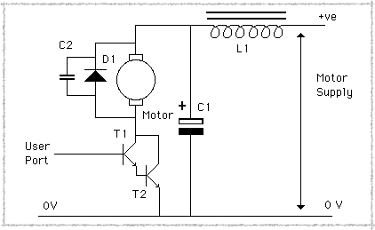
the power supplies are separate they have, and they need, a common ground. You can find a fuller discussion of de-coupling here but this is the sort of thing you can try:-
Basically a small capacitor across the motor will cut down some of the noise generated and the inductor and capacitor will stop the noise spreading to the rest of the circuits. The actual values of the capacitor are not too critical suffice it to say the bigger of each the better, start off with a .1uF capacitor across the motor and 47uF capacitor and 1mH inductor. You can leave the inductor out but don’t skimp on the capacitor.
Now, while this isolates the motor’s power supply to some extent it doesn't isolate it completely, there is always that common ground connecting them together. If you require total isolation you will have to use another technique, the two I want to look at here are mechanical isolation, and optical isolation.
Optical Isolation
Let’s look at optical isolation first this uses a component called an opto-isolator, I think you might be able to work out how it got it’s name. It consists of a light emitting diode (LED) next to a photo transistor. You pass current through the LED, it lights up and shines onto the photo transistor which then conducts or turns on. So the photo transistor needs
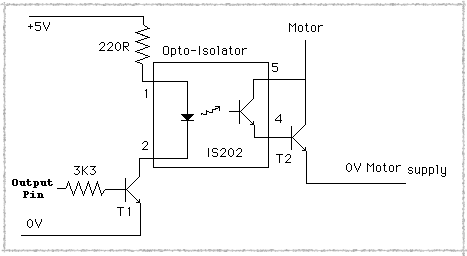
no electrical contact with the circuit controlling it. A typical arrangement is shown here:-
I have omitted the motor for simplicity but T2 controls the motor just like in the previous diagrams. There is a 220R (220 ohm) resistor to limit the current flow in the LED and a base resistor in T1, but there is no common ground needed. This keeps the two power supplies separate and prevents any conducted interference entering the Arduino or other circuits. There are lots of different opto-isolator available having different transfer characteristics, but most would work in this sort of application. You could even make your own using an LED and photo transistor placed in a light proof tube.
Speed Control
All of the above techniques can be used along with a PWM signal to control the motor’s speed. PWM stands for Pulse Width Modulation, and is a signal that stays not at a constant level but is rapidly being turned on and off.
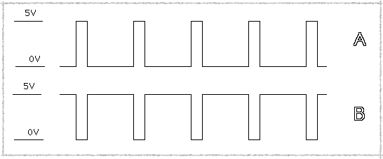
The ratio of the on time to the off time determines how much
power you are driving into the load and hence how fast it goes, like this:-
Waveform A is off most of the time and so will result in a slow speed, where as waveform B is on most of the time and so the motor will run faster. If this causes the motor to buzz then place a capacitor across the motor to smooth it out. Some of the Arduino outputs can be used as PWM outputs, this varies with the different model of Arduino so look to see what pins are supported by yours.
However, you can’t use this speed control method with the following mechanical relay techniques.
Mechanical Relay Isolation
Now let’s turn our attention to mechanical isolation or as it is better known a relay. This is an electro-magnet that attracts a lever connected to some contacts. On most relays there are at least five connections, two for the coil, and three for a single-pole, change-over set of contacts. These are labelled common, normally open and normally closed. In this context “normally” means the state the relay is in when the coil is not energised. So there is a connection between the common and normally closed even if the relay’s coil is not connected to anything. Incidentally the overwhelming majority of relays do not care what direction the current flows, so you can connect the coil up any way round. Using a relay you would wire it up like this:-
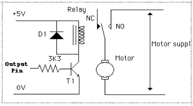
Note there is a diode across the coil just like the motor because the coil is an inductor. Note if you want the motor to be on all the time but have the Arduino turn it off then just use the NC (normally closed) contacts to connect up the motor power supply.
Some relays have more than one set of contacts, these are known as “poles”, if you have a relay with two poles you can control the direction of the motor by wiring it up like this:-
This has the current flowing through the motor in one direction when the relay is energised and the other direction when it is not, and the direction of current flow determines the direction of motor rotation.
Note the motor is always on, if you want control of the direction and the motor and also determine if the motor is on or off you need another relay. It only needs to be a single pole relay, you connect it like this:-
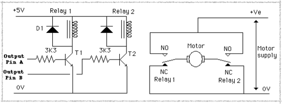
If the two relays are in the same state, that is both on or both off, then the motor is off. If the two relays are at a different state the motor is on. This has the added advantage that is when the motor is turned off the two connections to the motor are connected together. This makes the motor stop very quickly due to the effect known as “fly wheel braking”. The free running motor acts as a generator and the voltage produced is such that it causes the motor to try and rotate in the opposite direction, so this slows it down to a stop. This is the effect used to break electric underground trains and the spare electricity is actually pumped back into the supply grid. It is also used by some electric busses to charge up the battery when going down hill, very popular in Switzerland. This flywheel braking can be implemented electronically as well as by relays, but that’s another web page.
More from Mike Cook's Workshop!