Ethernet
ETHERNET INTERFACE BRICK AND SHIELD

This module or an Ethernet Shield] uses the W5100 chip which provides a set of TCP/IP protocols, MAC (Media Access) and PHY (Physical Interface) in one network chip, with support for the SPI bus interface.
The Ethernet Arduino IDE library that comes with the Arduino IDE is designed directly for W5100 and is supported on this product.
Your Arduino can be a Web Server with this brick! See an example HERE: But start out with "Your First Web Server" below.
NOTE: There are RED and GREEN versions of this module; they work and wire up the same..
There is on-board voltage regulation, so you can use 5-12V VCC input. The signal pins support both 3.3V and 5V levels.
The Ethernet Module has a standard RJ-45 connection, with an integrated line transformer. Another similar version exists with "Power Over Ethernet" connections that use the pins marked P+, P-, and G; this one does not use those.
NOTE: Most Ethernet Shields using the W5100 chip will work the same in the examples below.
W5100 Ethernet Module Information:
MODULE CONNECTIONS:

This shows a TOP view of the module connector. (If you have an Arduino MEGA, see the table below)
These connectors are numbered left-right, top-bottom starting at upper right. There is a small triangle marking pin 1.
 So, the connections are:
| PIN |
Function |
Arduino PIN |
Suggested Color |
MEGA Pin |
| 1 |
GND |
GND |
BROWN |
GND |
| 2 |
Vin 5V |
+5V |
RED |
+5V |
| 3 |
RESET |
RESET |
VIOLET |
RESET |
| 4 |
SS (Slave Select) |
10 |
ORANGE |
10 |
| 5 |
SCK (SPI Interface) |
13 |
YELLOW |
52 |
| 6 |
MOSI (SPI Interface) |
11 |
GREEN |
51 |
| 7 |
MISO (SPI Interface) |
12 |
BLUE |
50 |
| 8,9,10 |
No Connection |
N/C |
N/C |
 ARDUINO CONNECTIONS:

Pins 10,11,12 and 13 on an Arduino / YourDuino are used for the Ethernet Module as shown at the right.
NOTE: The Arduino Ethernet page makes this explanation of the Mega connections:
Arduino communicates with the shield using the SPI bus. This is on digital pins 11, 12, and 13 on the Uno and pins 50, 51, and 52 on the Mega. On both boards, pin 10 is used as SS.On the Mega, the hardware SS pin, 53, is not used to select the W5100, but it must be kept as an output or the SPI interface won't work.
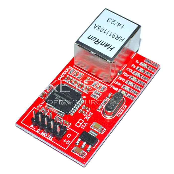 Informational LEDs:
- PWR: indicates that the module is powered
- LINK: indicates the presence of a network link and flashes when the shield transmits or receives data
- FDX: indicates that the network connection is full duplex
- SPD: indicates the presence of a 100 Mb/s network connection (as opposed to 10 Mb/s)
- RX: flashes when the shield receives data
- TX: flashes when the shield sends data
- COL: flashes when network collisions are detected
ARDUINO ETHERNET LIBRARY SOFTWARE:
Information about the Arduino Library is here:
Connect the module to your computer or a network hub or router using a standard ethernet cable (CAT5/CAT6 with RJ45 connectors). Connecting directly to a computer's Ethernet port may require the use of a cross-over cable (although many computers, including all recent Macs can do the cross-over internally).
Network Settings:
The module must be assigned a MAC address and a fixed IP address using the Ethernet.begin() function. A MAC address is a globally unique identifier for a particular device. Inventing a random one should work (or use the one in the example), but don't use the same one for multiple boards. Valid IP addresses depend on the configuration of your network. It is possible to use DHCP to dynamically assign an IP to the shield. Optionally, you can also specify a network gateway and subnet.
YOUR FIRST WEB SERVER:
- Connect your Arduino to your computer and a network cable to the Ethernet Brick.
- In IDE, make sure you have the right Board Type and ComPort set. Test with BLINK.
- In the Arduino IDE , open File>Examples>Ethernet>Webserver
- Look the the beginning of the sketch and find the line like this:
- IPAddress ip(192,168,1, 177);
- If you have a typical home network this is probably OK as is. Otherwise find the IP address of your computer and pick some address with the same numbers except the last one (use 177 there as an example).
- Click VERIFY to make sure it compiles OK
- Click UPLOAD and check to make sure it completes uploading
- Open your browser on your computer and type in the IP address (like 192.168.1.177) ENTER
- You may have to wait up to 5 minutes for your routers/switches to handle the New Guy On The Block...
- Then, you should see a page with 5 lines showing the Analog values on the 6 Analog inputs. If nothing is connected, the values will just change randomly. Connect a couple of jumpers to [GND and A0] (should read almost Zero) and [+5V to A3] (should read almost 1023).
- The Browser will keep asking for data automatically every 5 seconds and you should see the page update. Use jumpers to set a couple of Analog inputs to Gnd, +5V, 3.3V and see the results.
NOTES:
Make sure you open the Serial Monitor and see the startup; should show "server is at 192.168.1.177". If it shows 0.0.0.0 there is a connection problem.
Check the IP address your machine has (in details of ethernet adapter status). Probably like 192.168.1.(some low number). If it's a lot different you are on some other network segment. Make the IP in sketch agree in the first 3 parts. Sometimes it takes a few minutes for your network switch to find the adapter. Wait a few minutes..
When operating correctly the Serial Monitor will put out (and repeat) something like this:
server is at 192.168.1.177
new client
GET / HTTP/1.1
Host: 192.168.1.177
Connection: keep-alive
Cache-Control: max-age=0
Accept: text/html,application/xhtml+xml,application/xml;q=0.9,image/webp,*/*;q=0.8
Upgrade-Insecure-Requests: 1
User-Agent: Mozilla/5.0 (Windows NT 6.1; WOW64) AppleWebKit/537.36 (KHTML, like Gecko) Chrome/45.0.2454.85 Safari/537.36
Referer: http://192.168.1.177/
Accept-Encoding: gzip, deflate, sdch
Accept-Language: en-US,en;q=0.8

client disconnected
NEXT: An example Web Server that provides a web page showing Temperature, Humidity and Dew Point [/ethernet-temp-humidity is HERE:]
There are many examples in File>Examples>Ethernet and more below.
SOME TUTORIAL EXAMPLES:
Below are links to some tutorials are online articles about connecting Arduino to the Internet. "The Internet Of Things" refers to devices that are connected so they can be seen and controlled over the Net. Here's some perspective on that:
INTERNET OF THINGS
Other Tutorials:
INSTRUCTABLES Ethernet Tutorial
Pin Control Over the Internet – Arduino + Ethernet
Turn on a light, or 10. Arduino control over serial
Getting Data From The Web – Arduino + Ethernet
Moving Forward with Arduino – Chapter 16 – Ethernet
Web Controlled Arduino LED