LCD-Blue-I2C
LCD Displays (Blue and Yellow) with I2C/TWI Interface
NOTE! NOTE! MANY UPDATES 11/28/2020 moving to Perry LCD Library
IMPORTANT LCD Software Library INSTALL Info:
ALL these displays will now use the great Library written by Bill Perry . You can install the library from the Arduino Library Manager. In the Arduino software IDE, Use the top menu:
Tools and then Library Manager ... Then WAIT (It is slow) You should see this:
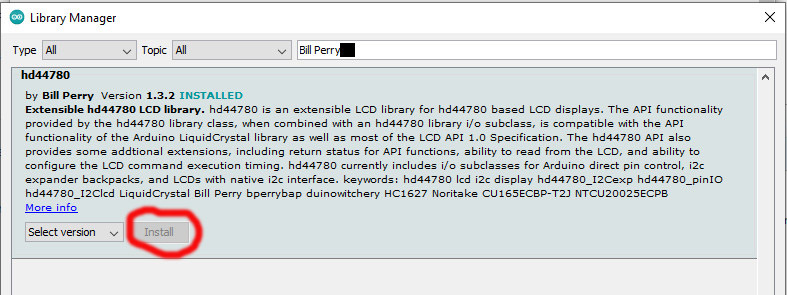
Now move your cursor to the field marked with red spot. .... WAIT until you see your cursor and you can type. Type "Bill Perry" and ... WAIT. You should see this:
Click on INSTALL. (It may be over on the right more like this:)  NOTE!! Move any other LCD libraries to another folder,or rename or delete them.
OK. With that library installed, let's connect your LCD I2C display.
NOTE!! Move any other LCD libraries to another folder,or rename or delete them.
NOTE! THERE ARE THREE (or More??) VERSIONS OF THE 2 and 4 LINE DISPLAYS. Check the small "backpack" interface board on the back. These small circuit boards on the back interface a 2-wire I2C "I Squared C" bus (plus Ground and +5V power) to the many pins on the LCD display itself. This allows running the display from only 2 signal pins on Arduino.
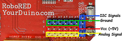
The YourDuino RoboRED (UNO Compatible) has a 4-pin connector that works well for this type display.
These displays are Available HERE:
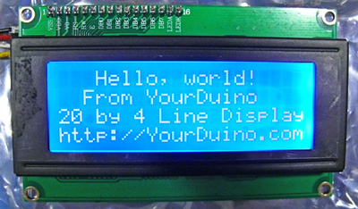
NOTE! These displays are very clear bright white on dark blue (or Black on Yellow) background: it is difficult to get a good digital photo due to polarization effects.
I2C ADDRESSES:
NOTE: With the Perry library you should NOT have to worry about I2C addresses ! But if you care, see:
I2C Address Scanner Sketch HERE The "backpack" modules used on these displays utilize the PCF8574A IC Chip. The Datasheet is HERE: File:Pcf8574a.pdf
The modules used on these displays may also be used for general-purpose 8-bit I/O expanders. A module with the address pins available is HERE These I2C interface displays have a built-in ADDRESS. If you try to run a display and there is no response or nothing is displayed you may have the wrong address in the code you are using. You can run the I2C ADDRESS SCANNER (Bottom of this page) on your Arduino to check the address on your display if necessary. For LOTS of detailed technical information about I2C Interfaces see THIS from Nick Gammon.
WHY THE I2C (IIC) TYPE LCD DISPLAY?
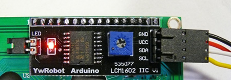
To use this type LCD directly with Arduino, you would need 6 pins: RS, EN, D7, D6, D5, and D4 to talk to the LCD. If you are doing more than a simple project, you may be out of pins using a normal LCD shield. With this I2C interface LCD module, you only need 2 lines (I2C) to display information. If you already have I2C devices in your project, this LCD module actually uses no more pins at all. More information about I2C/TWI (Wikipedia) This unit connects with 4 wires including Vcc and Gnd. It is easiest with a 4-wire cable that plugs into the [/SensorShield Sensor Shield] communications connector or directly to a YourDuino RoboRED (UNO Compatible: See it HERE (click)).. See the lower right: "I2C" 4-pin connector. But you can wire it directly yourself if needed: There are 4 pins on the display.. (see photo below)

|
UNO |
MEGA | |
|
SDA |
Analog 4 |
Pin 20 |
|
SCL |
Analog 5 |
Pin 21 |
On most Arduino boards, SDA (data line) is on analog input pin 4, and SCL (clock line) is on analog input pin 5. On the newer Arduino UNO (The "V3" pinout), the SCL and SDA pins are also on two new leftmost top pins. The YourDuino RoboRED has those pins and also a nice 4-pin connector arranged exactly like the LCD display pins. On the Arduino Mega, SDA is digital pin 20 and SCL is pin 21. NOTE: The Blue Potentiometer (Photo) adjusts Contrast. If you don't see any characters, adjust it. Start clockwise and back down to where the characters are bright and the background does not have boxes behind the characters.
EXAMPLE: See a LCD used in the Temperature-Humidity project.
Extensible hd44780 LCD library Functions HOW-TO
See Bill's documentation HERE: (Scroll down a little. Especially see the section API Summary. These are the commands you can use to control your LCD. In your code you will normally put lcd. at the beginning to make a complete command. Examples:
- lcd.begin(16,2); (For a 2 line 16 character LCD)
- lcd.begin(20,4); (For a 4 line 20 character LCD)
- lcd.setCursor(col, row); (Both Columns and Rows start at 0 origin, so the first column of the first row is lcd.setCursor(0, 0);
- lcd.setCursor(4,1); ( 5th character in second row).
- lcd.print("Hello!") (First you set the starting cursor position, right??)
- lcd.print(int 5); {Display a numeric value)
It will take some learning and experimentation to mix text and data on your LCD!
Below are Example Software Sketches for different displays. They will also display characters you type on the Serial Monitor screen on the LCD. NOTE: Line 1 only is correct when writing a long sequence of characters. The characters fill the first line and continue on the third, due to the way the LCD internal addressing works. So this is "normal" and has to do with the LCD hardware. Usually you will set the cursor position before writing characters. (Details in the document linked at the end of this page, if you want them.) (Cut and paste these examples into a blank page on the Arduino IDE).
I2C LCD DISPLAY VERSION 1:
 These type displays have the 4 pins in the right order to connect directly to the Yourduino RoboRED by a 4-pin cable.
I2C LCD DISPLAY VERSION 2:
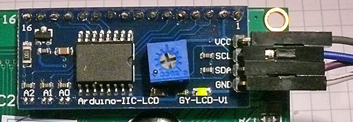 Marked "Arduino-IIC-LCD GY-LCD-V1" NOTE: The wire connections are in a different order! See the labels on the PC Board.
Example Software Sketch for 2 line 16 character Displays:
This sketch should work for almost all 2 line 16 character LCD displays with an I2C "Backpack" PC Board with PCF8574 chip on the back.
/* YourDuino.com Example Software Sketch
 *  _2_Line_I2C_Display_TestV2.ino
 *   16 character 2 line I2C Display
 *   Uses Bill Perry's HD44780 Library, which can be installed from the Arduino Library Manager
 *   See Bills documentation: https://github.com/duinoWitchery/hd44780
 *   See the "API Summary" section.  Use "lcd" in front like lcdbegin(cols, rows)
 *
 *   LCD Display Blue or Yellow: I2C/TWI "Backpack" Interface
 questions??  terry@yourduino.com

 */
 // ----------------------------------------------------------------------------
/*LiquidCrystal compability:
Since this hd44780 library is LiquidCrystal API compatible, most existing LiquidCrystal
sketches should work with hd44780 hd44780_I2Cexp i/o class once the
includes are changed to use hd44780 and the lcd object constructor is
changed to use the hd44780_I2Cexp i/o class.
*/

/*-----( Import needed libraries )-----*/
#include <Wire.h>
#include <hd44780.h>                       // main hd44780 header
#include <hd44780ioClass/hd44780_I2Cexp.h> // i2c expander i/o class header


/*-----( Declare Constants )-----*/
// LCD geometry
const int LCD_COLS = 16;
const int LCD_ROWS = 2;

/*-----( Declare objects )-----*/
hd44780_I2Cexp lcd; // declare lcd object: auto locate & auto config expander chip
/*-----( Declare Variables )-----*/
int status;

void setup()   /*----( SETUP: RUNS ONCE )----*/
{
  status = lcd.begin(LCD_COLS, LCD_ROWS);
  if(status) // non zero status means it was unsuccesful
  {
    // hd44780 has a fatalError() routine that blinks an led if possible
    // begin() failed so blink error code using the onboard LED if possible
    hd44780::fatalError(status); // does not return
  }
  Serial.begin(9600);

  // Print a message to the LCD.
  lcd.setCursor(0, 0);
  lcd.print("2-Line DISPLAY");
  delay(1500);
  lcd.setCursor(0, 1);
  lcd.print("YourDuino: HI!");

  delay(5000);
  lcd.setCursor(0, 0);
  lcd.print("Now YOU Type    ");
  lcd.setCursor(0, 1);
  lcd.print("On SerialMonitor");
}/*--(end setup )---*/


void loop()   /*----( LOOP: RUNS CONSTANTLY )----*/
{
  {
    // when characters arrive over the serial port...
    if (Serial.available()) {
      // wait a bit for the entire message to arrive
      delay(100);
      // clear the screen
      lcd.clear();
      // read all the available characters
      while (Serial.available() > 0) {
        // display each character to the LCD
        lcd.write(Serial.read());
      }
    }
  }

}/* --(end main loop )-- */

/*-----( Declare User-written Functions )-----*/


/* ( THE END ) */
Example Software Sketch for 4 line 20 character Displays:
This sketch should work for almost all 4 line 20 character LCD displays with an I2C "Backpack" PC Board with PCF8574 chip on the back.
/* YourDuino.com Example Software Sketch
 *  LCD_I2C_4x20_TEST.ino
 *   20 character 4 line I2C Display
 *   Uses Bill Perry's HD44780 Library, which can be installed from the Arduino Library Manager
 *   See Bill's documentation: https://github.com/duinoWitchery/hd44780
 *   See the "API Summary" section.  Use "lcd" in front like lcd.begin(cols, rows)
 *
 *   LCD Display Blue or Yellow: I2C/TWI "Backpack" Interface
 questions??  terry@yourduino.com

 */
 // ----------------------------------------------------------------------------
/*LiquidCrystal compability:
Since this hd44780 library is LiquidCrystal API compatible, most existing LiquidCrystal
sketches should work with hd44780 hd44780_I2Cexp i/o class once the
includes are changed to use hd44780 and the lcd object constructor is
changed to use the hd44780_I2Cexp i/o class.
*/
/*-----( Import needed libraries )-----*/
#include <Wire.h>
#include <hd44780.h>                       // main hd44780 header
#include <hd44780ioClass/hd44780_I2Cexp.h> // i2c expander i/o class header


/*-----( Declare Constants )-----*/
// LCD geometry
const int LCD_COLS = 20;
const int LCD_ROWS = 4;


/*-----( Declare objects )-----*/
hd44780_I2Cexp lcd; // declare lcd object: auto locate & auto config expander chip
/*-----( Declare Variables )-----*/
int status;

void setup()   /*----( SETUP: RUNS ONCE )----*/
{
  Serial.begin(9600);  // Used to type in characters

  lcd.begin(20,4);         // initialize the lcd for 20 chars 4 lines, turn on backlight

// ------- Quick 3 blinks of backlight  -------------
  for(int i = 0; i< 3; i++)
  {
    lcd.backlight();
    delay(250);
    lcd.noBacklight();
    delay(250);
  }
  lcd.backlight(); // finish with backlight on

//-------- Write characters on the display ------------------
  // NOTE: Cursor Position: Lines and Characters start at 0
  lcd.setCursor(3,0); //Start at character 4 on line 0
  lcd.print("Hello, world!");
  delay(1000);
  lcd.setCursor(2,1);
  lcd.print("From YourDuino");
  delay(1000);
  lcd.setCursor(0,2);
  lcd.print("20 by 4 Line Display");
  lcd.setCursor(0,3);
  delay(2000);
  lcd.print("http://YourDuino.com");
  delay(8000);
  // Wait and then tell user they can start the Serial Monitor and type in characters to
  // Display. (Set Serial Monitor option to "No Line Ending")
  lcd.setCursor(0,0); //Start at character 0 on line 0
  lcd.print("Start Serial Monitor");
  lcd.setCursor(0,1);
  lcd.print("Type chars 2 display");


}/*--(end setup )---*/


void loop()   /*----( LOOP: RUNS CONSTANTLY )----*/
{
  {
    // when characters arrive over the serial port...
    if (Serial.available()) {
      // wait a bit for the entire message to arrive
      delay(100);
      // clear the screen
      lcd.clear();
      // read all the available characters
      while (Serial.available() > 0) {
        // display each character to the LCD
        lcd.write(Serial.read());
      }
    }
  }

}/* --(end main loop )-- */


/* ( THE END ) */
Example: Display DS18B20 Temperature Sensors on LCD
See THIS PAGE
I2C ADDRESS DETAILS
I2C ADDRESS SCANNER FOR ARDUINO/YOURDUINO:
You can scan for the I2C address used by your display. Connect your display (See connection info at top of this page). Then upload the following sketch to your Arduino. Click on "Serial Monitor at upper right. Set the Speed (lower right pulldown) to 115200. Push the Reset button on your Arduino and see the results. The results should look like this (address changes):
 I2C scanner. Scanning ...
 Found address: 39 (0x27)
 Done.
 Found 1 device(s).
Copy and Paste this sketch (Thanks Nick Gammon!) into a blank Arduino IDE window:
// I2C Scanner
// Written by Nick Gammon
// Date: 20th April 2011

#include <Wire.h>

void setup() {
  Serial.begin (115200);

  // Leonardo: wait for serial port to connect
  while (!Serial)
    {
    }

  Serial.println ();
  Serial.println ("I2C scanner. Scanning ...");
  byte count = 0;

  Wire.begin();
  for (byte i = 8; i < 120; i++)
  {
    Wire.beginTransmission (i);
    if (Wire.endTransmission () == 0)
      {
      Serial.print ("Found address: ");
      Serial.print (i, DEC);
      Serial.print (" (0x");
      Serial.print (i, HEX);
      Serial.println (")");
      count++;
      delay (1);  // maybe unneeded?
      } // end of good response
  } // end of for loop
  Serial.println ("Done.");
  Serial.print ("Found ");
  Serial.print (count, DEC);
  Serial.println (" device(s).");
}  // end of setup

void loop() {}
CHANGING I2C ADDRESSES:
SOME I2C interfaces have pins (or solder pads) that can be changed to change the address. They are usually labelled A0-A1-A2 . Here's the way addresses change from a default 0x27 with if you connect address pads together. (1 = Not Connected. 0 = Connected):
|
A0 |
A1 |
A2 |
HEX Address |
|
1 |
1 |
1 |
0x27 |
|
0 |
1 |
1 |
0x26 |
|
1 |
0 |
1 |
0x25 |
|
0 |
0 |
1 |
0x24 |
|
1 |
1 |
0 |
0x23 |
|
0 |
1 |
0 |
0x22 |
|
1 |
0 |
0 |
0x21 |
|
0 |
0 |
0 |
0x20 |
If you make a change use the I2C Address Scanner to confirm it...
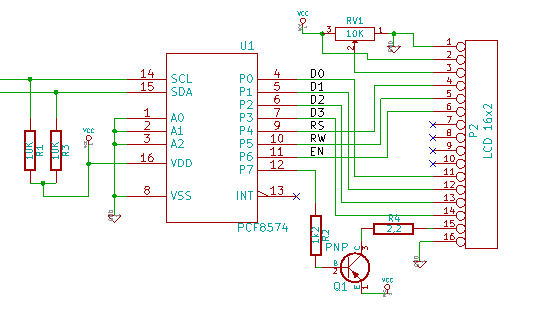
MORE INFORMATION ABOUT THE I2C "BACKPACK" USED ON THESE DISPLAYS: Schematic Diagram:
