Nrf24L01-2.4GHz-HowTo
RF24L01 2.4GHz Radio/Wireless Transceivers How-To
UPDATES: Comments, Critique to terry@yourduino.com mailto:terry@yourduino.com
- ALWAYS start with the simple Getting Started tests. THEN add your own code!
- PROBLEMS getting nRF24L01 Working: CLICK HERE
- Also see Robin's excellent "Simple nRF24L01+ 2.4GHz transceiver demo" HERE
- Pinout for TMRh20 Library useage added. See table below
- Example sketches: (TKFIX)
Having two or more Arduinos be able to communicate with each other wirelessly over a distance opens lots of possibilities:
- Remote sensors for temperature, pressure, alarms, much more
- Robot control and monitoring from 50 feet to 2000 feet distances
- Remote control and monitoring of nearby or neighborhood buildings
- Autonomous vehicles of all kinds
These are a series of low-cost 2.4 GHz Radio modules that are all based on the Nordic Semiconductor nRF24L01+ chip.
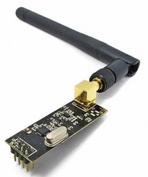
Info from the manufacturer: [1] The Nordic nRF24L01+ integrates a complete 2.4GHz RF transceiver, RF synthesizer, and baseband logic including the Enhanced ShockBurst™ hardware protocol accelerator supporting a high-speed SPI interface for the application controller. The low-power short-range (50-200 feet or so)Transceiver is available on a board with Arduino interface and built-in Antenna for less than $3! There is also a high-power version (right).
nRF24L01 Modules (Left to Right)
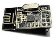
- With built-in Antenna
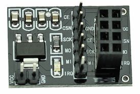
- Base module with voltage regulator and bypass capacitors for stability
- With added Transmit Power Amplifier, Low Noise Receiver Preamplifier, External Antenna
- Click images for details and example prices.** Widely available on Ebay, Amazon too.
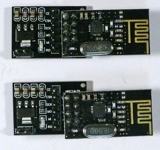
Below are a couple of kits with multiple nRF24L01 versions (Click on images for kit availability)
- 3 low-cost nRF24L01 with built-in Antenna, 2 base modules(left)
- 2 High Power nRF24L01 with external Antennas, plus 1 Low-cost nRF24L01, 2 base modules (right)
Examples of Arduino to nRF24L01 Connections (Pin Table with colors below):

NOTE! If using the Base Module, power it from 5V not 3.3 like in these photos...


NOTE! If using the Base Module, power it from 5V not 3.3 like in these photos...
Power_Problems:
Many users have had trouble getting the nRF24L01 modules to work. Many times the problem is that the 3.3V Power to the module does not have enough current capability, or current surges cause problems. Here are suggestions:

- Use the RF24 Library from TMRH20 (below) and set power low to minimize power requirements: radio.setPALevel(RF24_PA_MIN); Space the two radios about a meter apart. After you have things working, and if you know you have enough 3.3V current (up to 250 mA or more) then try higher power. The possibilities are: RF24_PA_MIN, RF24_PA_LOW, RF24_PA_HIGH and RF24_PA_MAX
- Connect a 3.3 uF to 10 uF (MicroFarad) capacitor directly on the module from +3.3V to Gnd (Watch + and - !) [Some users say 10 uF in parallel with 0.1uF is best] This is especially important if you are connecting the module with jumper wires. Or you are using the regular Arduino UNO which provides only 50 mA at 3.3V
- For testing try powering the nRF24 with a pair of AA alkaline cells (3v) with the battery GND connected to the Arduino GND.
- Use a[YourDuinoRoboRED]Arduino UNO compatible, which has an added 3.3V regulator (But add a .1 uF capacitor on the radio module).
- But the easiest and best solution is low-cost base module like this:[2] (RIGHT) that you can plug nRF24L01 modules into. These have a 3.3V regulator built in, AND good power bypass capacitors. You can also find these on Ebay etc. They make it easier to get started and keep operation reliable.
- A separate 3.3V power supply [this one?)]
- If you design a printed circuit board that the module plugs into, add .1uf and 10uf capacitors close to the GND and 3.3V pins. See the schematic of the base board shown on the right on [page.] as an example.
These instability problems are particularly noticeable when 3.3V power comes from a UNO, MEGA, Nano etc. that has only 50 ma of 3.3V power available. Newer boards like the [[3]] have 350 ma or more available and can run even the high-power modules directly.
nRF24L01 SOFTWARE AND LIBRARIES: (Jump Ahead IF you're ready for that...)
Range
Range is very dependent on the situation and is much more with clear line of sight outdoors than indoors with effects of walls and materials. The usual distance quoted by different suppliers for the low-power version module with the single chip is 200 Feet or 100 Meters. This is for open spaaaaaace between units operating at a Data Rate of 250KHz. Indoors the range will be less due to walls etc... The example with radio.setPALevel(RF24_PA_LOW); will be only 10 feet or so. But reliable. You can do these things to get better range:
- Make sure you have good 3.3V power (not just plain UNO, Mega etc. on USB power). You can use a separate 3.3V supply, or a Base Module powered from 5V that has a 3.3V regulator, or a YourDuino RoboRED.
- **After** you have **good** 3.3V power, set the RF "Power Amplifier Level" to MAX. Like this: radio.setPALevel(RF24_PA_MAX); Or try intermediate settings first: RF24_PA_MIN, RF24_PA_LOW, RF24_PA_HIGH and RF24_PA_MAX
- Set radio.setDataRate(RF24_250KBPS); //Fast enough.. Better range//
- // Set radio.setChannel(108); // 2.508 Ghz - Above most Wifi Channels
We suggest you test two units at your actual locations before making a decision. There are units with an Antenna Preamplifier for the receiver and transmitter power amplifier and external antenna. The range between that type unit and several low-power units will be better than between two low-power units. Every situation is a little different and difficult to get an exact number without actual tests.
[to nRF24L01+ Data Sheet.] You don't have to, but if you want to understand more about what you can do with this "little" radio, download the data sheet. In particular you may want to read pages 7-8-9 ( For Overview and Features), and page 39 (MultiCeiver, which allows 6 Arduinos to talk to a Primary Arduino in an organized manner). Fortunately the board-level products we have take care of many of the physical and electrical details and Antenna Impedance Matching etc., and this library takes care of lots of register initialization and operational details.
There are other types of nRF24L01 modules which add Transmitter power amplifiers and Receiver preamplifiers for longer distances.. up to 1 Km (3000 feet).
[them all here.]
These modules use an external antenna which can be a simple directly-attached one or a cable-connected antenna with more gain or directivity. Here's what some of these look like:


Above is the low-power version, with it's built-in zig-zag antenna. On the right you can see the pins sticking down (up in this photo) that connect to Arduino. Later we will show the pinout. **NOTE!! Different Libraries use different pinouts from nRF24L01 to Arduino!!**
File:NRF24L01-LN-PA-2.jpg width="370" height="267" File:NRF24L01-LN-PA-1.jpg width="290" height="405" File:NRF-Amp-Cable-1-1024.jpg width="480" height="309"
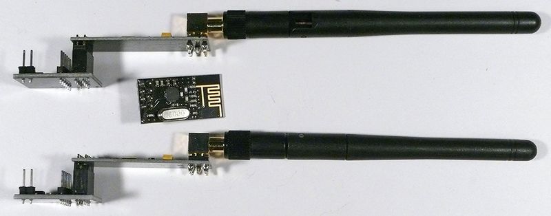
Above is the version with Transmit Power amplifier and Receive Preamplifier. Our low-cost antenna is on the unit in the middle. The same 8 pins connect to Arduino and the base module. Same software is used. On the right is the antenna connected with a 3M cable. Connectors are "Reverse SMA".
You might find a similar cable [[4]] Here's a [to a Home-Brew antenna design:]
These transceivers use the 2.4 GHz unlicensed band like many WiFi routers, BlueTooth, some cordless phones etc. The range is 2.400 to 2.525 Ghz which is 2400 to 2525 MHz (MegaHz). The nRF24L01 channel spacing is 1 Mhz which gives 125 possible channels numbered 0 .. 124. WiFi uses most of the lower channels and we suggest using the highest 25 channels for nRF24L01 projects.
Transceivers like these both send and receive data in 'packets' of several bytes at a time. There is built-in error correction and resending, and it is possible to have one unit communicate with up to 6 other similar units at the same time. The RF24 Network Library extends this to multiple 'layers' of interconnected transceivers.
These amazing low-cost units have a lot of internal complexity but some talented people have written Arduino libraries that make them easy to us. They all use the same pinout as shown in the following diagram, which is a TOP VIEW (Correction!):
 File:NRF24L012 BottomView.jpg align="right" caption="BOTTOM VIEW"
#po1
Here are details of the Pinout and connections to Arduino (updated):

| SIGNAL | MODULE PIN | Cable COLOR | Base Module PIN | Arduino Pin: TMRh20RF24 LIBRARY | Arduino Pin for RF24 Library | Arduino Pin for Mirf Library | MMEGA 2560 pin RF24 Library | Arduino Pin for RH_NRF24 RadioHead Library | MEGA 2560 Pin fir RH_NRF24 RadioHead Library |
|---|---|---|---|---|---|---|---|---|---|
| GND | 1 | Brown | GND | GND | GND * | GND | GND * | GND * | GND * |
| VCC | 2 | Red | VCC | **3.3 V** | 3.3V * | 3.3V | 3.3V * | 3.3V * | 3.3V * |
| CE | 3 | Orange | CE | **7** | 9 | 8 | 9 | 8 | 8 |
| CSN | 4 | Yellow | CSN | **8** | 10 | 7 | 53 | 10 | 53 |
| SCK | 5 | Green | SCK | **13** | 13 | 13 | 52 | 13 | 52 |
| MOSI | 6 | Blue | MO | **11** | 11 | 11 | 51 | 11 | 51 |
| MISO | 7 | Violet | MI | **12** | 12 | 12 | 50 | 12 | 50 |
| IRQ | 8 | Gray | IRQ | - | 2 | per library | N/C | N/C |
- NOTE!! Most * problems with intermittent operation are because of insufficient current or electrical noise on the 3.3V Power supply. The MEGA is more of a problem with this. Solution: ADD bypass capacitors across GND and 3.3V ON the radio modules **or use the Base Modules** shown above. One user said, "Just Solder a 100nF ceramic cap across the gnd and 3.3v pins direct on the nrf24l01+ modules!" Some have used a 1uF to 10uF capacitor.
- NOTE: Pin 8 IRQ is Unused by most software, but the RF24 library has an example that utilizes it.
The COLOR is for optional color-coded flat cable[such as THIS.] Photos above show an example.
NOTE: These units VCC connection //**must**// go to 3.3V not 5.0V, although the Arduino itself may run at 5.0V and the signals will be OK. The NRF24L01+ IC is a 3.3V device, but its I/O pins are 5 V tolerant , which makes it easier to interface to Arduino/YourDuino. Arduino UNO and earlier versions have a 3.3V output that can run the low-power version of these modules (See Power Problems at the top of this page!), but the high-power versions must have a separate 3.3V supply or use a Base Module with a 3.3V regulator. The [RoboRED] has a higher power 3.3V regulator and can be used to run the high-power Power Amplifier type module without a separate 3.3V regulator.
nRF24L01 SOFTWARE AND LIBRARIES:
We will show an example of transmit and receive software below, and there are many examples on the RF24 Library download page. You will need a library of software to run the nRF24L01 radios. There has been a progression of improvements to the RF24 libraries by many people. TMRH20 (Who IS he/she, anyway??) has done a great job on the current library and network additions. There are lots of details but you can ignore many of them that the library will take care of.
Get TMRh20's excellent RF24 Library that supports both Arduino and RaspberryPi:
** NOTE!! If you have an earlier version of an RF24 Library, COMPLETELY REMOVE IT and install this version. **
Read about it and Download it [HERE:] (Click "Download ZIP" on the upper right of the page) Read the detailed documentation [HERE] Read his BLOG with advanced projects [HERE] Once you have downloaded the ZIP, you should see a folder called RF24-master.ZIP. Change the name of this file to just RF24.ZIP. Double click on the ZIP and you should see a folder inside also called RF24-master. Rename this to just RF24 as well.
Then see our page about installing libraries [HERE:] When you have the library installed, you can run some examples. A ways below we discuss the individual commands (methods) in the RF24 Library and show how to use them to make a simple transmit-receive system. But to get you started we suggest you start with one of the Examples in the RF24 Library from TMRh20. See this page:
[EXAMPLES] When you install the RF24 library, those examples are loaded on your computer. You don't have to download them.
NOTE! If using an Arduino MEGA:
This works fine with Arduino MEGA. You just have to add the instruction line (in the setup line): pinMode(53,OUTPUT); So all examples given in this website or with the library will work with wiring to pins 7 and 8 like indicated, just add the OUTPUT mode for pin 53 (SS) when using Arduino MEGA.
We suggest you start with, um, "GettingStarted".** You need to set up two arduinos, with two nRF24L01's like in the photo above. Separate them by 5 feet or so, though. . You can run two instances of the Arduino IDE on the same machine, with two nRF24L01's on separate USBs with separate COM#. I suggest this sequence:
- Connect one nRF24L01 to your first Arduino according to the table ab ove (Use the TMRh20 RF24 Library column connections).
- Start the Arduino IDE .. connect the first Arduino with USB. Find the COM number (Tools>Port) and select it.
- Load the GettingStarted example (<File>Examples>RF24>) and make sure it compiles OK. UPLOAD to your Arduino
- Open the Serial Monitor (right side if the dark green bar) and SET IT TO 115200 . Close it and open it again. you should see:
- code
RF24/examples/GettingStarted
- PRESS 'T' to begin transmitting to the other node
- Connect the second nRF24L01 to your second Arduino with same connections according to the table above.
- Start __another__ instance of the Arduino IDE .. connect second Arduino with a second USB cable. Find the COM number (Tools>Port) and select it.
- Load the example and make sure it compiles OK. UPLOAD to your Arduino
- Open the Serial Monitor (right side if the dark green bar) and SET IT TO 115200 . Close it and open it again. you should see the Same output.
- Close the Serial Monitor, look at the code in the second IDE window and CHANGE one line to look like this:
- media type="custom" key="28211921"
- Upload that version to the second Arduino.
- Now, open both Serial Monitor windows, and type "T" in the top of the first Arduino window.
- You should see some thing like:
- code
RF24/examples/GettingStarted
- PRESS 'T' to begin transmitting to the other node
- CHANGING TO TRANSMIT ROLE -- PRESS 'R' TO SWITCH BACK
Now sending Sent 523513060, Got response 523511232, Round-trip delay 1828 microseconds Now sending Sent 524519544, Got response 524517728, Round-trip delay 1816 microseconds code
And the other Serial Port window should look like:
code RF24/examples/GettingStarted
- PRESS 'T' to begin transmitting to the other node
Sent response 523511232 Sent response 524517728 Sent response 525521620
You can reverse the actions by type R in the transmitting side and then T in the opposite side.
OK? You can always revert to this test when things seem to stop working. NOTE: See the "POWER PROBLEMS" section above if nothing works!
You can run some other examples, but when you want to understand the RF24 library and it's Methods better, see the section below.
See: Other Example Sketches at top of this page. Also see the very good example by Robin on [PAGE.]
The reader will find more details and additional examples here
RF24 LIBRARIES: Information, Documentation, Network, Mesh Network and more! TMRH20 has been busy!
[Library]: Main Page. Download ZIP file at right
 RF24 Library detailed [[5]]
 RF24 Library [Documentation] (details of a funcions and their valid parameters)
 RF24 Library [[6]] Many examples of the capabilities of the RF24 Library
 [Network System ] A many-node Network Library
 [library for mesh networking] A Mesh Network Library
[Library for transmitting Audio]
RF24 LIBRARIES: Commonly Used Commands (Methods):
- NOTE:** If you wish, see ALL the details [[7]]
We will try to understand the commands to set up and operate an nRF24L01 radio and build a very simple working example. First we will look at the minimum needed to set up and transmit or receive data. Later we will write more complete examples and get them working with real radios..
CREATE AND START UP A RADIO (For either transmit or receive):
Create a radio and set the Arduino pins to be used for CE and CS)
- EXAMPLE:** (Create an instance of a radio, specifying the CE and CS pins. )
RF24 **myRadio** (7,8); //"myRadio" is the identifier you will use in the following examples//
//**NOTE:** The following pins are fixed and unchangeable. AND Vcc (supply voltage MUST be 3.3V)// //SCK to Arduino pin 13// // MOSI to Arduino pin 11 // // MISO to Arduino pin 12 //
// **NOTE**: In all following commands, you must use the same identifying name you used in the RF24 statement that created the radio. ("**myRadio**" in the example above) You will use that identifier followed by (dot) followed by the method (command), followed by parameters. This is "object oriented programming". The OBJECT in this case is the Radio, and there are many METHODS that can operate on the Object. A METHOD is much like a Function or a Subroutine. //
// EXAMPLE: **myRadio.begin();** // Start up the actual radio module with the "begin" method
- NOTE:** "PIPES" : This is often confusing. nRF24L01 uses "pipes" that connect from transmitter to receiver. Pipes have an address you need to set. The Transmitter pipe must have the same address as the Receiver pipe. Later it's possible to use multiple "pipes" at once
- EXAMPLE OF RECEIVING DATA:**
- myRadio.openReadingPipe ** (1, const uint8_t *address) Pipe number (usually 1), pipe address (which is usually 5 bytes in an array structure).
- EXAMPLE:**
byte addresses[][6] = {"1Node"}; Create address for 1 pipe.
- myRadio.openReadingPipe**(1, addresses[0]); //Use the first entry in array 'addresses' (Only 1 right now)//
//**myRadio.** **startListening** (); Turn on the receiver and listen for received data. You MUST have opened a reading pipe FIRST. //
//if( **myRadio.available**())// Check for available incoming data from transmitter
{
while **(myRadio.available**()) //While there is data ready//
//{//
// **myRadio.read**( &myData, sizeof(myData) ) ; // Get the data payload (You must have defined that already!)
}
- myRadio.stopListening();** //stop listening//
//**EXAMPLE OF TRANSMITTING DATA:**// byte addresses[][6] = {"1Node"}; Create address for 1 pipe.
- myRadio.openWritingPipe**(1, addresses[0]); //Use the first entry in array 'addresses' (Only 1 right now)//
// **myRadio.writ**e( // &myData, sizeof(myData) // ) //
We have written working examples of Transmit and Receive sketches using these methods. See them HERE
SET SOME OTHER OPERATING OPTIONS AND PARAMETERS:
NOTE: Many of these methods have default values you can usually use.
- radio.printDetails**();
Prints out a LOT of debugging information.
**radio.setDataRate**(RF24_250KBPS);
speed RF24_250KBPS for 250kbs, RF24_1MBPS for 1Mbps, or RF24_2MBPS for 2Mbps. 250K Bits per second gives longest range.
**radio.setPALevel**(RF24_PA_MAX);
Set Power Amplifier (PA) level to one of four levels: RF24_PA_MIN, RF24_PA_LOW, RF24_PA_HIGH and RF24_PA_MAX The power levels correspond to the following output levels respectively: NRF24L01: -18dBm, -12dBm,-6dBM, and 0dBm 0 dBm is equal to 1 milliwatt. Each 3 dB is a 2:1 ratio. 6 dB is 4:1 10 dB is 10:1 So -18 dBm is 0.0000158489 watts ! To calculate all this dBm Stuff (Which us old Radio Engineers love) See [[8]] The "High Power" nRF24L01 modules [THIS] have a gain of 100, so their output is +20 dBm (100 milliwatts)
**radio.setChannel**(108);
Which RF channel to communicate on, 0-124 Can operate on frequencies from 2.400GHz to 2.524GHz.
Programming resolution of channel frequency is 1Mhz
This is the same unlicensed band WiFi operates in (WiFi uses 2.400 to 2.500 gHz). Usually frequencies above channel 100 are best.
- NOTE: In most countries the allowed frequencies are from 2.400GHz to 2.483.5GHz which you must not exceed. In USA it's best to use channels from 70 to 80.**
You can scan the channels in your environment to find a channel that is clear... See this Scanner sketch.
**radio.enableDynamicPayloads**();
Enable custom length payloads on the acknowledge packets. Ack payloads are a handy way to return data back to senders without manually changing the radio modes on both units.
- radio.setRetries ** (15,15);
Set the number and delay of retries upon failed transmit. P arameters:
delay: How long to wait between each retry, in multiples of 250us, max is 15. 0 means 250us, 15 means 4000us.
count: How many retries before giving up, max 15
**radio.setCRCLength**(RF24_CRC_16);
length: RF24_CRC_8 for 8-bit or RF24_CRC_16 for 16-bit Cyclic Redundancy Check (Error checking)
//NEWS: RaspberryPi is now supported! I need to show a working example... Phew..//
RadioHead: A very full-featured Library with support for may different radios, not just nRF24L01:
[[9]]
#ex1
Another interesting example: Chat between radios: https://github.com/stanleyseow/RF24/tree/master/examples
[is another good How-To example ]from Robin on arduino.cc
---------------------( COPY: Post for people having nRF24L01 Problems )---------------------
nRF24L01 Intermittent / No operation.
ALWAYS check 3.3V power. Many times intermittent operation is due to power supply regulation issues. Even though the average current may be less than 15ma, apparently there are quick transients when each transmit burst happens. The first examples in the RF24 TMRH20 library run low power and this is less of a problem.
 I used to have nRF24L01 problems. Worked one day / one minute, failed the next. Now I put a 0.1uf AND 10uf capacitor right from GND to 3.3V pins on the modules, and things are MUCH better. An excellent solution is the base module shown at the top of this page.
 These modules are designed to plug into a baseboard that usually has significant bypass capacitors. If you have them on the end of jumper wires you need extra bypass capacitors.
 Try it and let us know here!
 -----------------( END COPY )----------------------