Using NodeRED on Raspberry Pi for Relay and LED Control
Introduction
.png)
Node-RED is a flow-based development tool for visual programming developed originally by IBM for wiring together hardware devices, APIs and online services as part of the Internet of Things (IoT).
Node-RED provides a web browser-based flow editor. It consists of a Node.js-based runtime where you use a web browser to access the flow editor which can be used to create JavaScript functions. Elements of applications can be saved or shared for re-use. Within the browser you create your application by dragging nodes from your palette into a workspace and start to wire them together. With a single click, the application is deployed back to the runtime where it is run.
The palette of nodes can be easily extended by installing new nodes created by the community and the flows you create can be easily shared as JSON files.
Flow-based Programming
Invented by J. Paul Morrison in the 1970s, flow-based programming is a way of describing an application’s behavior as a network of black-boxes, or “nodes” as they are called in Node-RED. Each node has a well-defined purpose; it is given some data, it does something with that data and then it passes that data on. The network is responsible for the flow of data between the nodes.
It is a model that lends itself very well to a visual representation and makes it more accessible to a wider range of users. If someone can break down a problem into discrete steps they can look at a flow and get a sense of what it is doing; without having to understand the individual lines of code within each node.
In this project, we are going to use Node-RED control an LED and a relay which are connected to Raspberry Pi GPIOs.
Hardware Needed
- Raspberry Pi 3 (Raspberry Pi Zero W would work too)
- At least, 8GB C10 microSD card
- Raspberry Pi 5V, 2A recommended power adapter
- 5mm LED
- 220 ohm resistor
- Jumper wires
- 5V relay module
- 3rd-party PC for editing the Node-RED flows in a web browser
Software Needed
- PuTTY for accessing the Raspberry Pi over ssh
- SD Card Formatter for formatting the microSD card
- Etcher for writing an image unto the microSD card
- Raspbian Stretch Lite
Methodology
Using Raspberry Pi in Headless Mode without a Wired Network Interface
You can use the Raspberry Pi in Headless mode and access it via SSH (using a software like PuTTY) without any wired interface (like a LAN connection from the Raspberry Pi to the Router, in which the remote computer that would be accessing the Raspberry Pi via SSH.

Follow these steps:
- Insert the microSD card to a computer through an microSD card adapter
- Format the microSD card and write the Raspbian Stretch OS to the SD card
- Open the boot drive of the SD card (i.e. the root directory as seen on a PC mounting the SD card) that appears in "This PC" directory of a windows PC and create an empty file called SSH with no file extension.
- Also create a file named wpa_supplicant.conf. This is a configuration file for wireless access. Copy and paste the text below to the file:"Your_Network_Name" represents the name of the name of the Wi-Fi. It is case-sensitive and character-sensitive. "Your_Network_Password" represents the password of the Wi-Fi network.
ctrl_interface=DIR=/var/run/wpa_supplicant GROUP=netdev
update_config=1
country=US
network={
    ssid="Your_Network_Name"
    psk="Your_Network_Password"
    key_mgmt=WPA-PSK
}
- Save (ctrl+o) and exit (ctrl+x)
- Insert the microSD card into the Raspberry Pi and power it up
- Make sure the router or mobile hotspot used in the wpa_supplicant.conf is turned ON, then connect the 3rd-party PC to the same hotspot

- Obtain the IP address of the Raspberry Pi; if using an Android phone, go to Settings → Wireless & networks → Tethering & portable hotspot → Portable WLAN hotspot → Device list
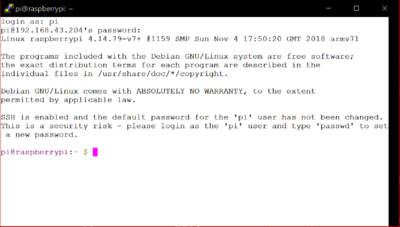
- Open PuTTY and type the IP address of the Raspberry Pi to access it via SSH
- A terminal would open. The default username is pi and the default password is raspberry (Note: The username and password are case-sensitive. It is advisable to change them immediately)
- To enable ssh, it is necessary to go into the Pi's configuration settings. Type
sudo raspi-config. Go to Interfacing Options → SSH → Yes.


Reboot the Pi and login again using PuTTY
Installing Node-RED on Raspberry Pi
Before installing Noode-RED, ensure the Pi is updated and upgraded:
sudo apt-get update && sudo apt-get upgrade
The recommended way to install Node-RED on Pi is to use the script below:
bash <(curl -sL https://raw.githubusercontent.com/node-red/raspbian-deb-package/master/resources/update-nodejs-and-nodered)
Start Node-RED
node-red-start
Use
node-red-pi --max-old-space-size=256
if having memory constraints on the Pi i.e. if there is not much available RAM on the Pi.
If you want Node-RED to run when the Pi boots up you can use
sudo systemctl enable nodered.service
Use this to disable auto-start when the Pi boots up:
sudo systemctl disable nodered.service
Use this to stop Node-RED
node-red-stop
Designing a Flow to Control Relay and LED
The Node-RED editor window consists of four components:
- The header at the top, containing the deploy button, main menu, and, if user authentication is enabled, the user menu.
- The palette on the left, containing the nodes available to use.
- The main workspace in the middle, where flows are developed by dragging nodes from the palette and wiring them together. The workspace has a row of tabs along the top; one for each flow and any subflows that have been opened.
- The sidebar on the right.

It is necessary to have the hardware ready before designing the Node-RED flow. Set up the circuit as shown:
Notice that the Vin of the relay module is connected to the 3.3V Pin of the Pi instead of the 5V Pin. This is because the voltage level for a digital HIGH (1) state in the raspberry Pi is 3.3V as opposed to the 5V of the Arduino. A digital LOW (0) signal is use to trigger ON the relay while a digital HIGH (1) signal is used to trigger OFF the relay. Therefore, in order to trigger OFF the relay with the digital HIGH signal from the Pi which is 3.3V, it is necessary to set it's Vin to 3.3V to make this the reference signal for the digital HIGH.
It is necessary to install the Node-RED dashboard nodes to enable you design a better user interface (UI).
To achieve this, follow these steps:
- Navigate to the Node-RED directory
cd ~/.node-red/
- Install the dashboard nodes on the Pi using the PuTTY terminal
sudo npm install node-red-dashboard
- Open a web browser such as Google Chrome or Mozilla Firefox and type in the IP address of the Pi followed by ":1880 for example, 192.168.43.204:1880. A page similar to this should be displayed, which would let you design your Node-RED flows:

- From the dashboard category of the palette, drag and drop the switch node onto the workspace

- Double-click on the switch node on the workspace to edit the properties
- Click on the Group bar to add new ui_group

- Type in the desired name and click on the Tab drop-down arrow to add new ui_tab

- Type in the desired name and click Add → Add

- Change the ON Payload and OFF payload to string

- Set the ON Payload value to 0 and the OFF Payload value to 1. This is because the relay is triggered ON by a digital LOW signal (0) and triggered OFF by a digital HIGH signal (1). You can adjust this according to the type of relay being used in the project.

- Set the Label (the text that would appear beside the switch button) and the Name (the text that would appear as the heading)

- Click on Done
- From the Raspberry Pi category of the palette, drag and drop the Raspberry Pi output node onto the workspace

- Double-click on the node to edit its properties

- Set the pin to Pin 5 (GPIO03)
- Check the initialize pin state?; set initial level of pin - high (1) and click Done

- Join the switch node to the PIN node by clicking on the dot at the right of the switch node and dragging it to the dot on the PIN node

- Click on deploy
- Open a new tab on the browser and append /ui to the initial url, e.g 192.168.43.204:1880/ui
- A user interface would show up which would be used for the control

See demo: https://www.youtube.com/watch?v=EiZz06cRKVY
Please email comments, critiques, suggestions and questions to: terry@yourduino.com