YourDuinoStarter-ButtonInput
Jump to navigation
Jump to search
ButtonInput

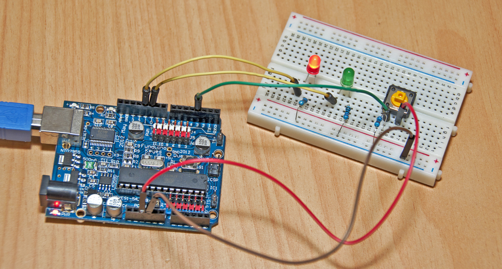
This software sketch gets you started with hooking things up. There is a photo/diagram below showing you how to do this. This reads one pushbutton switch as an Input Sensor, Decides if the button is being pressed or not, and takes the Action of turning one LED ON and the other OFF. Other simple input devices like a Tilt Switch or Photoresistor may be used in place of the pushbutton switch.
CONNECTIONS:
- Pushbutton Switch from +5 to Pin 3
- 10K Resistor from Pin 3 to ground
- LED and 220 ohm resistor in series from pins 10 and 11 to Gnd
NOTE: The longer lead of the LEDs goes towards the Arduino pins 10 and 11.
(Copy the text in the box below and Paste it into a blank Arduino IDE window)
/* YourDuinoStarter Example: Button Input
 - Reads state of Pushbutton, changes state of 2 LEDS
 - SEE the comments after "//" on each line below
 - CONNECTIONS:
 - Pushbutton Switch from +5 to Pin 3
 - 10K Resistor from Pin 3 to ground
 - LED and 220 ohm resistor in series from pins 10 and 11 to Gnd
 - V1.00 09/17/12
 Questions: terry@yourduino.com */

/*-----( Declare Constants and Pin Numbers )-----*/
#define buttonPin  3    // Pins to connect to
#define ledPin1    10
#define ledPin2    11

void setup()   /****** SETUP: RUNS ONCE ******/
{
  pinMode (ledPin1,OUTPUT) ;        // PIN 10 is an OUTPUT
  pinMode (ledPin2, OUTPUT) ;       // PIN 11 is an OUPUT
  pinMode (buttonPin, INPUT) ;      // PIN 3  is an INPUT
}//--(end setup )---


void loop()   /****** LOOP: RUNS CONSTANTLY ******/
{
  if  (digitalRead(buttonPin)==HIGH)  // IF button is pushed
  {
    digitalWrite(ledPin1, HIGH) ;         // LED1 ON
    digitalWrite(ledPin2, LOW) ;          // LED2 OFF
  }
  else
  {
    digitalWrite(ledPin1, LOW) ;          // LED1 OFF
    digitalWrite(ledPin2, HIGH) ;         // LED2 ON
  }
  delay(50);  // Switch may be "bouncing". Wait a bit

}//--(end main loop )---