InfraredBeamPair
INFRARED BEAM PAIR: TRANSMITTER-RECEIVER
This product is available here . (click)
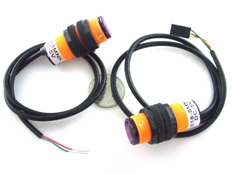
(There are no connectors preinstalled)

SIZE: 18mm (0.7 inches) diameter, with threaded nuts to mount in a panel or bracket. 46 mm (1.8 inches) long.'
This infrared beam-type system is composed of two nodes: a transmitter and a receiver. The transmitter outputs modulated infrared light (in a 15 degree angle cone). The infrared receiver light-sensitive element detects the transmitted beam of infrared light. The system uses 38 KHz modulated signals for long distance performance.
If the light path between the transmitter and receiver is blocked, then the receiver can not receive the transmitter, and it detects that an object exists in the path.
It is necessary to ensure that the transmitter and receiver are aligned in a straight line. This system usually works well at distances of up to 8 meters. Longer distances may work if there are not other significant IR sources, and the system is indoors.
The transmitter usually does not need to be controlled, so we can use any available 5V power supply.
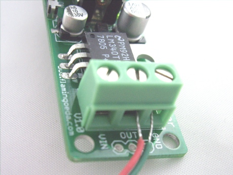
The green wire is to be connected to power supply module (GND), while the red line will be connected to 5V power supply module output (+). The photo shows an example power supply (not included with this product):

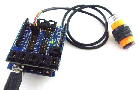
Connection of the receiver with Arduino is made with a 3-wire cable. The color sequence is: GND (green), 5V (red) and signal (yellow): The plug can directly connect to a Sensor Shield.

TESTING
The beam pair can actually be tested simply with 5v power: green to ground and red to +5 volts on both transmitter and receiver. The Transmitter LED should light all the time. The Receiver LED will light when it is NOT receiving and is blocked from the transmitter. The Receiver led will go out when the beam from the transmitter is received. The signal polarity is HIGH when the beam is seen and LOW when the beam is blocked.
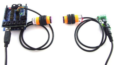
Here is a connection example: on the right is the infrared transmitter, its power from the 5V power supply module, on the left is the IR receiver.
Here is our test code used by the infrared receiver which will control the pin 13 digital I / O connected LED as an indicator of the beam being broken.
/* YourDuino Electronic Brick Test
 Infrared Beam Pair INPUT DEVICES
 terry@yourduino.com */

/*-----( Declare Constants )-----*/
#define SWITCHPIN 7
#define LEDPIN    13

/*-----( Declare Variables )-----*/
int  detector_state;  /* Holds the last state of the switch */

void setup()   /*----( SETUP: RUNS ONCE )----*/
{
  detector_state = 0;
  pinMode (SWITCHPIN, INPUT );
  pinMode (LEDPIN, OUTPUT );
}/*--(end setup)---*/

void  loop ()  /*----( LOOP: RUNS CONSTANTLY )----*/
{
  detector_state = digitalRead (SWITCHPIN);
  if ( HIGH == detector_state)
  {
    digitalWrite (LEDPIN, HIGH );
  }
  else
  {
    digitalWrite (LEDPIN, LOW );
  }
  delay (100);
}/* --(end main loop )-- */

/* ( THE END ) */
