MotorDrivers
MOTOR DRIVERS:
Arduino can drive many kinds of motors. But the low-power signals from Arduino need to control high-power circuits to run the actual motors. Here we will give examples of ways that Arduino can control different types of motors of different sizes.
If you are new to this subject, you may want to look at these two basic tutorials on DC motors that Mike Cook has contributed:
DC-Motors
See THIS Link
DC-Motors-2
And THIS LINK
And also StepperMotors this Stepper Motor information:
A Motor Driver will usually be a circuit board with several electronics components on it, including a high-power motor driver chip or some power transistors. (Examples Here:) Boards like this cost about $10 to $15 these days.
The following two boards use the L298N Chip. More about it on [/L298N-DataSheet THIS PAGE.]
Down below is information on a standalone [/MotorDrivers#L298Board L298 Motor Driver Board] (Not a plug-on Shield).
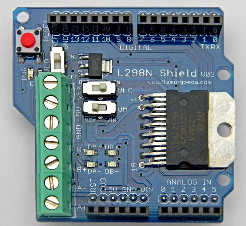
Motor Driver Shield
Here's an example of an Arduino "Shield" that plugs on top of an Arduino.This uses a motor driver chip L298N which we will detail more about later. Details of operation of the L298N Arduino Motor Driver Shield are [/ArduinoShieldL298n-2 HERE:] NOTE: This "shield" version is now hard to find. The module below is often used.
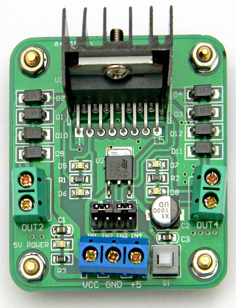
Stand-alone Motor Driver board (Available HERE)
This includes a heat sink for the L298N chip, allowing higher currents. It is also less expensive than a shield version. Often it can be mounted near the motors
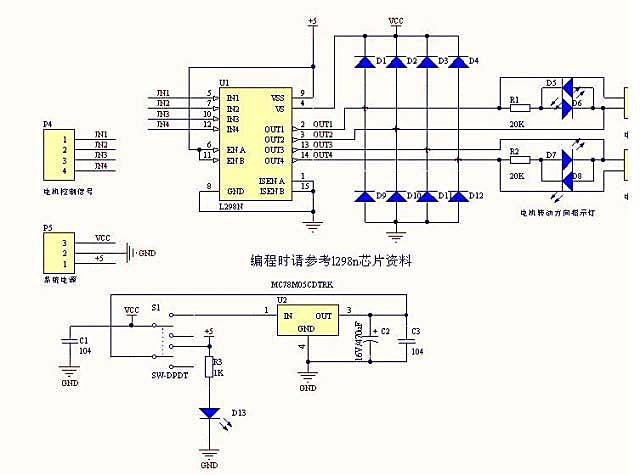
  Here's the schematic diagram for that board:

  Here are the specifications:
- Driver: L298N Dual H Bridge DC Motor Driver IC
- Motor Power Supply Vs: +5 V to +35 V
- Max average current 2A
- peak current Io: 3A
- Logic Level Power Vss: +5 V ~ +7 V (Onboard 5V Regulator can be used if Motor Power is > 7.0V)
- Logic level power: 0 ~ 36mA
- Logic signal input range:[ Low:-0.3V ≤ Vin ≤ 1.5V] [ High: 2.3V ≤ Vin ≤ Vss]
- Maximum power dissipation: 20W (when the temperature T = 75 ℃)
- Driver Board Size: 55mm * 49mm * 33mm (with fixed copper pillar and the heat sink height)
- Driver Board Weight: 33g
- LED direction indicators
- Logic power source switch. (DOWN for onboard Regulator, UP for 5V Vcc on both motors and logic)
2 DC Motors may be connected to the outputs on the right. Arduino controls the inputs so that the motor terminals are connected to Ground or Vcc (Motor Power Supply). So voltage can be applied in either direction through the motors, or both terminals can be connected to Ground to stop.
The "Enable" inputs EN A and EN B can be connected to an Arduino "PWM" pin to control motor speed.
It is also possible to use all 4 outputs at once to operate a single Stepper Motor.
Note the measures taken here to control "Back EMF" and "power supply noise" as mentioned in the tutorial [/DC-Motors (DC Motors)]. There are 8 diodes that are connected from the motor outputs to ground and the motor power supply. These are to limit or "snub" the back EMF voltages that otherwise would damage the chip. The diodes on the right side are LEDs that light up when the motors are powered and indicate what direction the current is flowing. There is also a +5 volt regulator chip (MC78M05) which supplies +5 volts to the L298N chip.
Details of operation of the L298N Arduino Motor Driver Shield are [/ArduinoShieldL298n-2 HERE:]


