Arduino-Project-Home-Monitor-Control
Arduino-Project-Online-Home-Monitor-Control
NOTE!! The "Cayenne" System shown below has been DISCONTINUED. An update using different interface will need to be done..
DO NOT ATTEMPT TO USE THIS PROJECT

To Cayenne Community: Comments, suggestions to terry@yourduino.com
This project uses a YourDuino RoboRED (or Arduino UNO With Sensor Shield) to monitor the temperatures in a home. This is especially useful for people like me who live in rural Vermont and heat mostly with wood, with a small backup propane furnace. When I travel for several days it's important to be able to remotely monitor temperatures and make sure the furnace works and the house is not freezing!
UPDATE: This has been rewritten for the current MQTT Cayenne system.
OBJECTIVES:
- Quick and Easy to build electrically and mechanically
- Easy creation of good graphical interface online
- No need for opening router ports, manual network configuration
- User defines widgets for online page
- Free for personal use
- Measure temperatures:
- Outdoor
- Indoor / Living Room
- Cellar
- Remote control of furnace to increase temperature before arriving home :-)
- Remote control of two relay-operated 5000W electrical heaters if necessary or furnace fail.
Building the system
It took about 10 hours to build and program the basic system and get it online. Physical build was simplified and will be shown below.
NOTE: The code below used the DS18B20 library function " sensors.getTempFByIndex" So you will have to identify each sensor by touching it to see which one changes.. Later we will show how to use address-identified DS18B20's so sensors are pre-identified.
Internet Of Things:
The secret to the easy online interface is the system created by mydevices.com called Cayenne. The user interface can be a browser online from anywhere, or Apps for Apple IOS or Android for mobile use. We'll walk through the electronics and physical build and the Cayenne interface builder. This assumes you have an internet connection and an ethernet port on a router or switch.
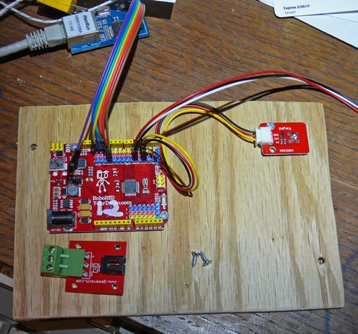
To avoid metalwork and allow quick but secure construction I used a 5 by 8 piece of 1/4 inch plywood as the base. See THIS PAGE for details of this approach. Here's what it looked like starting out:
Parts Used:
- Yourduino RoboRED (Arduino UNO Compatible) with easy-to-wire 3-pin connectors on every I/O pin.
- A 5 by 8 inch piece of 1/4 inch plywood as the base
- #4 by 3/8 Inch small wood screws and Velcro to attach modules
- A W5100 based Ethernet module
- "Rainbow" cable (7 wires used to connect Ethernet Module)
- 3-wire cables that plug into the RoboRED
- A 3-wire cable-to-terminal strip block
- Three waterproof DS18B20 temperature sensors: 1 with 1 Meter cable and 2 with 10 meter cable
- A bright LED module for testing control operation
- A 4-channel opto-isolated relay board to:
- remotely change furnace temperature setting
- remotely turn on 5000 watt electric heater in Kit Build area
- remotely turn on 5000 watt electric heater in Shop area
- Spare Relay Channel
- 40 feet of twisted-pair cable (I used ethernet cat-5) going to remote relay for furnace and heater contactors.
- Ethernet cable reaching to your router or switch
- 9V 1A plug-in power supply for Arduino
- 5V 1A plug-in power supply for opto-isolated relay
Physical Construction:
Here are some construction views:
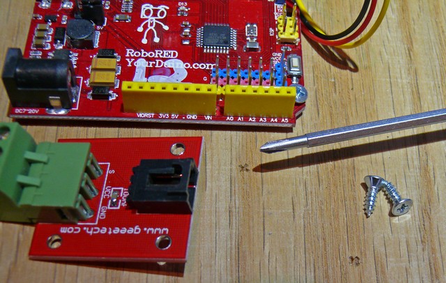
On the left you can see two marks where my small phillips screwdriver was used to locate the two screws that will hold the terminal module in place.
The plywood was hit with sandpaper on the edges for 60 seconds and 2 holes were drilled to screw it to a wall. Here you see the RoboRED screwed down to the base. The ethernet module is at top right of the photo. Upper left is a bright LED module for testing. Lower right is a terminal strip module used to connect to the DS18B20 temperature sensors. Everything just plugs together except the temperature sensor cables were soldered to be secure.
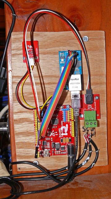
On the right is the completed system mounted on the end of a bookcase. The Rainbow cable makes it easier to get the ethernet module connections right, and the 3-pin cables plug in the LED and Terminal strip. At the lower right the three temperature sensor cables are held in place with staples (could use a cable clamp). The DS18B20 sensors are just connected in parallel and have a 5K pullup resistor from 5V to the signal pin. The 9V plug-in power supply is connected to the usual Arduino External Power connector. I already had holes going down to the cellar for other cables and a small plastic conduit to the outdoors for the outdoor sensor. The livingroom sensor is looped just at the top of the photo.
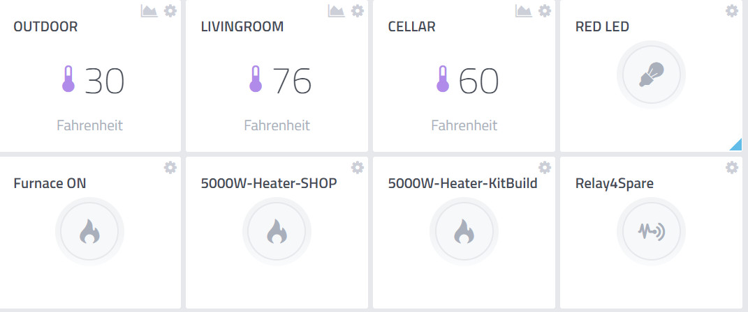
The online internet screen looks like this (below)

SEE LIVE ACTION OF SCREEN (READ-ONLY, Sensors Only, no control allowed!) CLICK HERE
Arduino Sketch Code
Cayenne builds most of the Arduino code. Below is the version running now. Cayenne allows you to add widgets to your dashboard to control any Arduino digital I/O pins . The "pushbuttons" can be clicked to turn the Red LED or the Furnace or the 5000W electrical heaters On.
/* YourDuino Example: Cayenne Internet Of Things "Home Monitor"
  - WHAT IT DOES  Connects to the Cayenne IOT service at https://cayenne.mydevices.com
  - See Example Cayenne Dashboard HERE:
 https://cayenne.mydevices.com/cayenne/dashboard/arduino/56590790-cdb5-11e8-a08c-c5a286f8c00d
  - Displays temperature from DS18B20 sensors, 1-wire bus on digital pin 4
  - Allows control of LED on digital pin 2
  - SEE the comments after "//" on each line below
  - CONNECTIONS:
   - W5100 Internet module (Uses pins 10-11-12-13)
   - DS18B20s with 4.7K Pullup resistor to pin 4
   - LED with resistor for testing outputs to pin 2
   - 4-channel Opto-isolated relay on Pins 5-6-7-8 for controls
      - Furnace low thermostat OR High Thermostat
      - 5000 Watt electrical heater 1
      - 5000 Watt electrical heater 2
      - Spare relay

  - V2.03 10/11/2018
   Questions: terry@yourduino.com


  This example shows how to connect to Cayenne using an Ethernet W5100 shield and send/receive sample data.
  The CayenneMQTT Library is required to run this sketch. If you have not already done so you can install it from the Arduino IDE Library Manager.
  Steps:
  1. Set the Cayenne authentication info to match the authentication info from the Dashboard.
  2. Compile and upload the sketch.
  3. A temporary widget will be automatically generated in the Cayenne Dashboard. To make the widget permanent click the plus sign on the widget.
*/

//#define CAYENNE_DEBUG          // Uncomment to show debug messages
//#define CAYENNE_PRINT Serial  // Comment this out to disable prints and save space (Uses 95% with this out)


#define RELAY_ON  0  //Optically Isolated relay board is ACTIVE LOW
#define RELAY_OFF 1

//****( These pins are used for digital input/output functions )
#define RED_LED_PIN       2
#define UNUSED_PIN3       3
// Digital pin the 1-wire bus and DS18B20s are connected to.
#define ONE_WIRE_BUS_PIN  4  // Define the 1-wire bus. Used for DS18B20 temperature sensors

#define FURNACE_ON_PIN    5  // Relay 1 (Optically-isolated 4- Channel Relay Board)
#define HEATER5000_1_PIN  6  // Relay 2
#define HEATER5000_2_PIN  7  // Relay 3
#define RELAY_4_UNUSED    8  // Relay 4
#define UNUSED_PIN9       9

// Digital pins for the W5100 Ethernet Interface  (Automatically managed by the library)
#define SS   10  //These pins not useable for anything else !
#define MOSI 11
#define MISO 12
#define SCK  13

// Virtual Pins for the DS18B20 temperature sensor widgets.
#define VIRTUAL_PIN1 V1
#define VIRTUAL_PIN2 V2
#define VIRTUAL_PIN3 V3


/*-----( Import needed libraries )-----*/
#include <CayenneMQTTEthernet.h> // from the Arduino Library Manager.

// Install the DallasTemperature library (http://milesburton.com/Main_Page?title=Dallas_Temperature_Control_Library#Code.2FLibrary)
// from the Arduino Library Manager. (Includes 1-wire library)
#include <DallasTemperature.h>

/*-----( Declare objects )-----*/
OneWire oneWire( ONE_WIRE_BUS_PIN);   // Create the 1-wire bus
DallasTemperature sensors(&oneWire);  // Create the sensors object (can be used with more than oneDS18B20 senso


// Cayenne authentication info. This should be obtained from the Cayenne Dashboard.
char username[] = "6f8ac6f0-e355-11e6-a446-0d180dc59d42";
char password[] = "39f26ec085433f46d13de612b2a5f241cb7a9f0d";
char clientID[] = "56590790-cdb5-11e8-a08c-c5a286f8c00d";

void setup()   // Runs ONCE at startup
{
//  Serial.begin(9600);
  Cayenne.begin(username, password, clientID);
  sensors.begin();        // Start the DallasTemperature Library running
  //---( Set the relay bits to be RELAY_OFF before switching pins to Outputs)
  digitalWrite(FURNACE_ON_PIN, RELAY_OFF);
  digitalWrite(HEATER5000_1_PIN, RELAY_OFF);
  digitalWrite(HEATER5000_2_PIN, RELAY_OFF);
  digitalWrite(RELAY_4_UNUSED, RELAY_OFF);
  //---( Now set the pins as outputs)
  pinMode(RED_LED_PIN, OUTPUT);
  pinMode(FURNACE_ON_PIN, OUTPUT);
  pinMode(HEATER5000_1_PIN, OUTPUT);
  pinMode(HEATER5000_2_PIN, OUTPUT);
  pinMode(RELAY_4_UNUSED, OUTPUT);
}// END setup

void loop() {
  Cayenne.loop();
}// END loop


// Default function for sending sensor data at intervals to Cayenne.
// You can also use functions for specific channels, e.g CAYENNE_OUT(1) for sending channel 1 data.
CAYENNE_OUT_DEFAULT()
{

  // Write data to Cayenne in the Cloud here. This example just sends the current uptime in milliseconds on virtual channel 0.
  Cayenne.virtualWrite(V0, millis());


  // Send the command to get temperatures.
  sensors.requestTemperatures();
  // Send the temperatures in Fahrenheit
  Cayenne.fahrenheitWrite(V1, sensors.getTempFByIndex(0));
  Cayenne.fahrenheitWrite(V2, sensors.getTempFByIndex(1));
  Cayenne.fahrenheitWrite(V3, sensors.getTempFByIndex(2));

}

// Default function for processing actuator commands from the Cayenne Dashboard.
// You can also use functions for specific channels, e.g CAYENNE_IN(1) for channel 1 commands.
CAYENNE_IN_DEFAULT()
{
  //  digitalWrite(RED_LED_PIN,CAYENNE_IN_4);
  CAYENNE_LOG("Channel %u, value %s", request.channel, getValue.asString());
  //Process message here. If there is an error set an error message using getValue.setError(), e.g getValue.setError("Error message");
}

CAYENNE_IN(V4)
{
  digitalWrite(RED_LED_PIN,  getValue.asInt());
}


CAYENNE_IN(V5)   // Following relay pins are ACTIVE LOW
{
  if ( getValue.asInt() == 0)
    digitalWrite(FURNACE_ON_PIN, HIGH);
  else
    digitalWrite(FURNACE_ON_PIN, LOW);
} // END V5


CAYENNE_IN(V6)
{
  if ( getValue.asInt() == 0)
    digitalWrite(HEATER5000_1_PIN, HIGH);
  else
    digitalWrite(HEATER5000_1_PIN, LOW);
} // END V6


CAYENNE_IN(V7)
{
  if ( getValue.asInt() == 0)
    digitalWrite(HEATER5000_2_PIN, HIGH);
  else
    digitalWrite(HEATER5000_2_PIN, LOW);
} // END V7


CAYENNE_IN(V8)
{
  if ( getValue.asInt() == 0)
    digitalWrite(RELAY_4_UNUSED, HIGH);
  else
    digitalWrite(RELAY_4_UNUSED, LOW);
} // END V8
Steps:
NOTE: To be updated!
0. Install the Cayenne Library (http://mydevices.com) from the Arduino Library manager.
1. Install the OneWire library (http://www.pjrc.com/teensy/td_libs_OneWire.html) from the Arduino Library Manager.
2. Install the DallasTemperature library (http://milesburton.com/Main_Page?title=Dallas_Temperature_Control_Library#Code.2FLibrary) from the Arduino Library Manager.
3. In the Cayenne Dashboard add new DS18B20 widgets.
4. Set the widgets to Value Display.
5. Select Virtual Pins and virtual pin numbers.
6. Set VIRTUAL_PINn to the pin numbers you selected.
7. Attach DS18B20s to a digital pin on your Arduino.
Schematic:
[Ground] -- [DS18B20] --[Digital Pin]-- [4.7k resistor] -- [5V]
8. Set the ONE_WIRE_BUS_PIN constant to match the pin used to connect the DS18B20.
9. Set the token variable to match the Arduino token from your own unique Dashboard.
10. Compile and upload this sketch.
11. Once the Arduino connects to the Dashboard it should automatically update the DS18B20 widget with data.
12. Add widgets (generic digital I/O) for Furnace ON, 5000Watt Heater#1, 5000 watt Heater#2, Spare relay
NOTE: A project must be online and running to add/edit widgets
13. Drag/move onscreen widgets as you wish
zz


