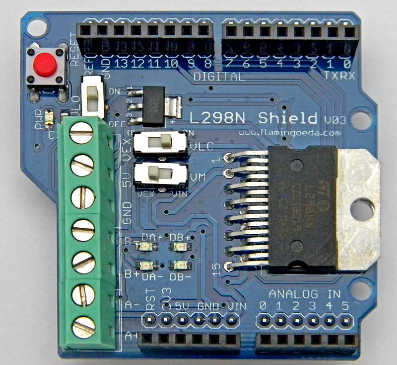
ArduinoShieldL298N
Arduino L298N Motor Drive Shield
L298N is a high voltage, high current motor driver chip, with the highest working voltage of 46V, continuous operating current of 2A, and instantaneous peak current up to 3A. The chip contains two "H bridges" which are high-voltage and high current full-bridge drivers that can directly drive two DC motors.
Arduino L298N motor drive expansion board V03
V03 is the most recent version. The main changes are to add switches to more easily meet the application requirements of different motors and applied voltages.
There is also a popular low-cost version as a module. See HERE

Two different voltages are needed for the operation of this board: +5 V for the logic part and the Motor Power, which may be from 5 to 30+ volts. There are different ways of getting the needed +5 V for the chip. Here are the different switches available:
- VLO (Logic Voltage: Onboard Regulator)
Motor Driver IC L298N needs two voltage: logic voltage and motor voltage. The logic voltage is 5V, usually less than the motor voltage (eg 7.2V, 9V or 12V). To convert the motor terminal voltage VEX into useful 5V logic voltage, the motor driver board provides a voltage regulator circuit, which is activated by turning the VLO switch on.. However this voltage regulator can only be run from Voltage less than 20V., so if the motor is greater than 20V, you can not use a voltage converter circuit.
- VLC (Logic Voltage Connected)
The L298N can also use +5V logic power from the Arduino. In this case, the VLC switch is turned on
- VM (Voltage Motor):
VM is the motor voltage selection. There are two ways to provide power for the motor: Vin pin through the Arduino board (switch in the VIN position) and from the VEX terminal (switch in the VEX position .)
Different Voltage Combination Scenerios:
1. The motor voltage is 6 ~ 12V
In general, Arduino can use 6V-12V from external power supply (connected to the Vin pin). If you have a motor voltage within this range, it just can used as the external power supply to both the Arduino and motor power. In this case set the switches:
- VLO: OFF, no use of voltage regulator
- VLC: ON, and the Arduino's 5V pin connector for expansion boards will provide the motor drive logic voltage
- VM: VIN, and the Vin pin on Arduino will be connected to the motor drive
external image shield_l298n_v03_4.JPG
2. The motor voltage less than 6V
This case can only be extended through the motor drive board GND and the VEX two terminals to supply to the motor, then motor drive expansion board 5V logic voltage converter circuit does not work (VEX voltage is too low), so we only with the Arduino board connected to 5V pin expansion boards available for the motor drive voltage of 5V logic. In this case the motor-driven expansion board is set to:
- VLO: OFF, no use of voltage regulator
- VLC: ON, and the Arduino's 5V pin connector for expansion boards will provide the motor drive logic voltage
- VM: VEX, motor power through the VEX / GND terminals
external image shield_l298n_v03_5.JPG
3. The motor voltage is 12V-20V
The logic supply voltage can come from the onboard regulator. Switch settings:
- VLO: ON, onboard voltage regulator used
- VLC: OFF, not used
- VM: VEX, motor power through the VEX / GND terminals
external image shield_l298n_v03_6.JPG
4. The motor voltage is 20V-46V
The onboard voltage regulator can not be used because motor supply voltage is too high.
- VLO: OFF, no use of voltage regulator
- VLC: ON, and the Arduino's 5V pin connector for expansion boards will provide the motor drive logic voltage
- VM: VEX, motor power through the VEX / GND terminals
external image shield_l298n_v03_7.JPG
IV / 099
L298N Circuit Operation:
Each DC motor is controlled by two pins to control the motor direction of rotation, and one pin on the PWM signal to control motor speed.
The direction of the motor MA controlled by Arduino pins 13 and 12 .
MA speed controlled by the Arduino's pin 10 .
The direction of the motor MB controlled by Arduino pins 11 and 8 .
MA speed controlled by the Arduino's pin 9 .
Sample code is as follows:
Motor A
int dir1PinA = 13;
int dir2PinA = 12;
int speedPinA = 10;
motor B
int dir1PinB = 11;
int dir2PinB = 8;
int speedPinB = 9;
unsigned long time;
int speed;
int dir;
void setup ()
{
pinMode (dir1PinA, OUTPUT);
pinMode (dir2PinA, OUTPUT);
pinMode (speedPinA, OUTPUT);
pinMode (dir1PinB, OUTPUT);
pinMode (dir2PinB, OUTPUT);
pinMode (speedPinB, OUTPUT);
time = millis ();
speed = 0;
dir = 1;
}
void loop ()
{
analogWrite (speedPinA, speed);
analogWrite (speedPinB, 255 - speed);
/ / set direction
if (1 == dir)
{
digitalWrite (dir1PinA , LOW);
digitalWrite (dir2PinA, HIGH);
digitalWrite (dir1PinB, HIGH);
digitalWrite (dir2PinB, LOW);
}
else
{
digitalWrite (dir1PinA, HIGH);
digitalWrite (dir2PinA, LOW);
digitalWrite (dir1PinB, LOW);
digitalWrite (dir2PinB, HIGH);
}
if (millis () - time> 5000)
{
time = millis ();
speed + = 20;
if (speed> 255) {speed = 0;}
if (1 == dir)
{dir = 0;}
else
{dir = 1;}
}
}
The board has four LEDs to denote the direction of rotation of the motor, and the brightness level is proportional to motor speed.
external image l298N_shield_7.png