Basic-StarterSet-Components
Jump to navigation
Jump to search
| YourDuino.com Basic Starter Set Components Comments or Questions: Terry@YourDuino.com or MaryAlice@YourDuino.comhttp://arduino-info.wikispaces.com http://arduinoinfo.mywikis.net/wikifile/view/YourDuino%20Basic%20Starter%20Kit%20Components.pdf/417760986/YourDuino%20Basic%20Starter%20Kit%20Components.pdf PDF Download HERE] | |
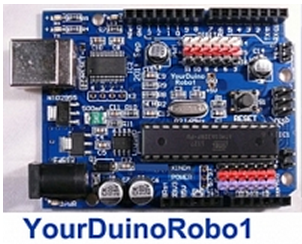
| YourDuinoRobo1 Arduino-compatible with built-in 3-pin I/O connectors, higher current 3.3V supply Upgraded Arduino Compatible: with ATMEGA328 Processor. BOTH 5.0V and 3.3V Operation with onboard regulator. | |
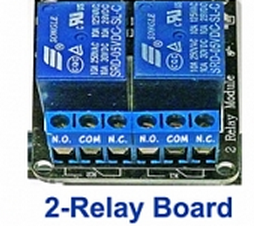
| Opto-Isolated 2-channel Relay Board With high-current relay, AC250V 10A ; DC30V 10A More information about controlling power with relays Here: https://arduinoinfo.mywikis.net/wiki/ArduinoPower | |
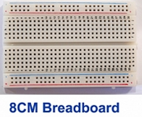
| 8CM Breadboard Breadboard with power and Ground busses. This is used to make quick and easy and usually non-permanent connections between Arduino and different electronics components, chips, resistors, LEDs etc. | |
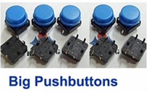
| (5) Big push-button switches [Digital Input] These large 12mm pushbutton switches have a nice CLICK action. They plug into the Breadboard. | |
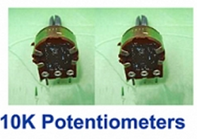
| (2) 10K Potentiometers that fit breadboard well [Analog Input] These can plug into the breadboard and can be turned by hand. | |
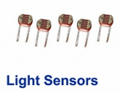
| '(5) 10K PhotoResistors (Light sensors) [Analog Input] PhotoResistor type 5516 5-10K'. These are small Photoresistors that have a resistance of 10K ohms at 10 lux. | |
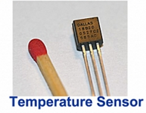
| Digital temperature sensor DS18B20 [Digital Signal Input] "1-Wire" Digital Temperature sensor. CONNECTIONS: (Holding chip with pins down, label towards you) - Left pin: Ground - Right pin: +5V Center pin: Signal | |
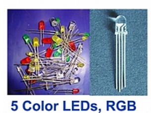
| (10) LEDs of 5 different colors, plus 220 ohm resistors [Digital or Analog Output] 1 RGB LED ( Red-Green-Blue Multicolor ) [Digital or Analog Output] RGB CONNECTIONS: NOTE: Hold RGB LED with pins down and longer pin second from the Left. 4 Pins in order left-right: - Left: RED - Second: +5V "Common Anode" - Third: BLUE - Right: Green | |
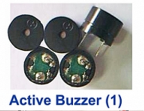
| Buzzer Module (makes sound with voltage applied) [Digital Output] This small sound module can be driven by an Arduino output pin.When the pin is set to HIGH (with the - terminal of this module grounded) it puts out a constant buzz or beep. | |
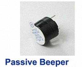
| Beeper Module (Makes different sounds/tones with Arduino TONE Library) [Analog Output] This small sound module can be driven by an Arduino output pin. The + pin is marked on the case. A pulse of current will make it click. A series of pulses will cause it to output a tone, and you can control the frequency. | |
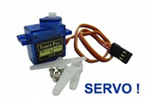
| Servo Motor (Mechanical positioning from digital pulses] [Digital Signal Output] The 3-pin connector plugs into the YourDuinoRobo1 connectors | |
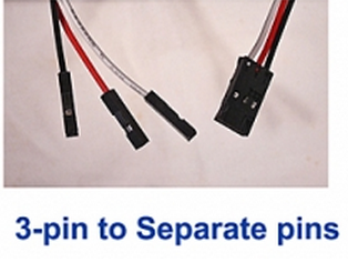
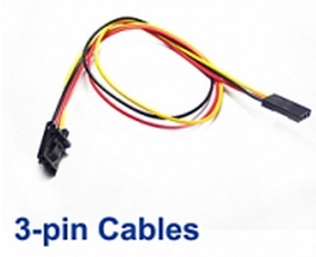
| 3-pin cable to separate wire ends that connect the Robo1 to any device Connections: Black=Ground, Red=Power, White/Yellow = signal | |
| 3-pin cables with 3-pin connectors that fit the Robo1 and various Electronic Bricks etc. Connections: Black=Ground, Red=Power, White/Yellow = signal | |
|
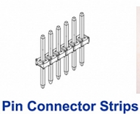
Connector Strip | |
|
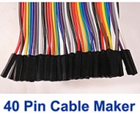
40 wire flat rainbow color cable “CableMaker” that can be separated to make many different cables | |
