ArduinoPower
Arduino Power !

(Power Switching devices for Arduino)
Left-Right: (ABOVE) A "relay electronic brick", a 4-relay board, an 8-relay optically-isolated board, a 4-Power-FET "brick"
AND there is Powering Arduino Itself: (Different Subject!)
Controlling Power With Arduino
Having your Arduino control higher-power devices like lights, motors, pumps, doors, and many more is one of the most interesting and useful applications you may get involved with. But it can be a little difficult and possibly dangerous when power line voltages are being controlled. There are significant differences in controlling AC power compared to DC. And there are considerations about different kinds of loads and so forth. This section will cover many of these subjects, show several available devices you can connect to Arduino to control power (examples above), and provide examples of working projects.
(Please direct questions, critiques and suggestions to: terry@yourduino.com )
NOTE: Sometimes switching lights, motors, etc. with relays can cause Electromagnetic Interference (EMI). More information about what to do in these cases is available HERE:
Please read This Electrical Safety and Disclaimer page before using any of these devices.
MENU: Jump to sections
- Arduino By Itself: Pin Current Limitations (Link to page)
- Arduino Controlling Higher Power: A simple example
- More_Complex_Systems: 2,4,8 relays
- "Optical Isolation"
- AC vs DC: Why do I care?
- DC Switching
- Power Control: Dimming / Speed
- 120-240 VOLTS Solid State Relays - AC Power Control: ON-OFF
A simple example:
Get your Arduino plugged into your main computer, and download the Good Old Blink Program. If you need help getting started, http://arduinoinfo.mywikis.net/wikiGettingStarted-Software go here...] You should have the LED on your Arduino blinking ON for 1 second, OFF for 1 second.
Now, what if you want to have a large light blink on and off like that?? First, let's look at ways of physically plugging things into Arduino.
Pins, Bits and All That:
You should be getting familiar with Arduino and it's pin connections.
So what's this stuff all about??
- PINS
- BITS
- ONES and ZEROS
- HIGH and LOW...
If you're pretty familiar with those words and ideas, fine. But if you'd like to learn a little more before we continue, jump over here and then come back...
Arduino Connection Options:

There are a few different ways of connecting devices to Arduino's I/O and Analog pins:
- Plug small wires or pins on the ends of wires into the black holes of the Arduino connectors and run them directly to the devices.
- Plug small wires or pins on the ends of wires into the Arduino and then into a "Solderless Breadboard" where other devices can be plugged in and connections made. (Example)
- Plug a circuit board (usually called a "Shield") on top of Arduino, plugging into most or all Arduino pins. These Shields are usually special-purpose add-ons to Arduino to do things like control robot motors, connect to the Internet, etc.(Examples).
- Use an Arduino-compatible board like the YourDuinoRoboRed which has many added connectors to make plugging devices easy.
- Plug a special "Sensor Shield" [(Example)] on top of Arduino that gives you the 3-pin connectors like a YourDuinoRoboRED. IF you have a larger board like an Arduino or YourDuino MEGA, you'll need a MEGA sensor shield to make the many pins easily useable. . Then you can easily plug cables and other devices into all the Arduino I/O, Analog and Communications ports. You can also plug in cables from many different devices in the form of "Electronic Bricks" http://arduinoinfo.mywikis.net/wiki/ElectronicBricks-1 (Example)], to quickly try out different options and test and develop software.
NOTE: We have a Page on cables and connections HERE:
Example- Blink a table lamp:

OK, if you have the Blink program running, a small LED is blinking on your Arduino. Here, we have plugged a Sensor Shield on top of the Arduino, and plugged in a small Electronic Brick with a short cable. Now there is a small LED ("L" on the red relay brick) blinking on and off the same as the LED on Arduino. And if you listen you can hear the relay clicking on and off too. A Relay is a switch that is operated by an electromagnet. (More about relays). In this example, our Arduino has the very easy job of driving a 10,000 ohm resistance with Digital I/O Pin 13. The http://arduinoinfo.mywikis.net/wiki/ElectronicBricks-1 Electronic Brick system] is an easy way to connect dozens of different devices to Arduino and try them out or make working systems. But you can make many of these circuits yourself if you want, and they are good examples.
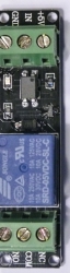
Let's look in more detail at the Relay Brick:

The Relay Brick does this in two steps. Let's look at a diagram of what's on that little Brick: First, notice the cable connector has a standard pattern of wires: Ground-Voltage-Signal (see the GVS labels on the Sensor Shield above). So the brick has +5 volt power available. Here's what happens:
- When the Blink Software Sketch does " digitalWrite(13, HIGH); " the Arduino connects the Signal wire to HIGH, which is +5 Volts.
- +5 volts flow through 10,000 ohm resistor R1 to the Base of transistor Q1, and a current of about .0005 amps (500 microamps) flows and turns the transistor ON.
- The transistor connects one end of the electromagnet inside the relay to Ground (the other end is already connected to 5 volts), and a current of about .07 amps flows. We say the transistor has a Current Gain of more than 100.
- The electromagnet pulls the switch contact inside and moves it to connect the COM terminal to the NO (Normally Open) terminal.
- A Lamp, or other load, is connected by the relay contacts. Let's say it might be a 100 watt lamp.
- Details: the diode across the electromagnet conducts in the reverse direction when the transistor is turned off to protect against a voltage spike.
- Details: An LED and it's current limiting resistor are also connected across the electromagnet and it lights up when the relay is turned on. Just for you...
This is the way high power can be controlled by a very small power from Arduino. Let's quickly think about the numbers:
- Arduino outputs 5 Volts at .0005 amps. Multiply and that's .0025 watts (2.5 milliwatts) Not Much!
- The transistor controls 5 Volts at .07 amps. That's, um, .35 watts.
- The relay controls, say, 220 Volts at .5 amps. That's 110 watts.
So with this little brick, Arduino controls a power 4400 times it's own power. That's what this power control stuff is all about.
How Relay Contacts Work:

Look at the photo of a relay above. Notice the 3 screw-type terminals. They are labelled "NO", "COM", "NC". Those labels mean:
- NO: Normally Open
- COM: Common Connection
- NC: Normally Closed
Look at the diagram on the right. This shows the switch that is inside the relay. This switch is "thrown" by the electromagnet inside. The diagram shows that COM is connected to the Normally Closed contact. That's the case when the relay is off. When the relay is turned on the electromagnet flips the switch up and COM is then connected to Normally Open. So, if we want a lamp to be on when the relay is on, we connect our circuit from COM to NO. Let's try that out.
- More About Relays HERE:
- Good detailed RELAY Information and Tutorial here:
- NOTE: Sometimes switching lights, motors, etc. with relays can cause Electromagnetic Interference (EMI). More information about what to do in these cases is available HERE:
Using two typical SPDT (Single Pole Double Throw) relays to control a DC motor:

DC Motors can be controlled to Run in either direction or stop, with two relays. See the diagram on the left. When both relays are off, both motor terminals are connected to the same point and the motor is stopped. If one relay is activated, one motor terminal is connected to the opposite polarity and it runs in that direction. If the other relay is activated, the motor connected in the opposite polarity. (If Both relays were activated the motor would also stop!).
NEXT: Blinking a Lamp on and off:
OK, we have the relay clicking on and off. Inside, the COM terminal is connected to the NO (Normally Open) terminal when the relay is on. So all we have to do is use that switch to turn the lamp on and off.
We're going to use a low-voltage lamp from IKEA, to make things a little safer. IF you wire this type relay to switch "Mains Voltage" (115V in USA and others, 220V in Europe and others) you MUST take precautions. READ THIS DISCLAIMER! We will simply cut one side of the cable to the lamp, and route that connection through the relay from COM to NO. Here's the way that looks: And if we draw that as a schematic diagram it would be something like this:{TBD}

More_Complex_Systems:
Here are Optically-Isolated Relay boards in 1,2,4 and 8 relay versions: (clickable)

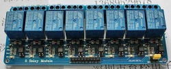
If you do something a little bit more complex, like controlling an aquarium, a plant growing system, or a home energy management system, you'll need more relays. Let's look more closely at the relay boards shown above. (You can get them here).
And you can see their schematic diagrams on the product pages. You can build these circuits yourself if you wish, or prototype things like the examples here.
IMPORTANT NOTE: There is a issue with start-up of Arduino programs that control these relays. All of these 2,4, or 8 relay boards input controls are Active LOW, meaning that setting a pin LOW turns them ON. To assure that no relays activate at Reset or Power-On until you want them to, the initialization sequence in SETUP should be:
- digitalWrite(Relay, HIGH);
- pinMode(Relay, OUTPUT);
This design is intentional, so that it is possible to guarantee that at power-on of a system, or system reset, that no relays activate except when expected under program control. There may be pumps, lights etc attached and chaos could ensue if this was not controlled definitively for each output port being used. Then in the main Loop section turn relays On or Off as needed... Following is an example program that properly controls 4 relays on our 4-relay board (Available HERE )
Arduino Software Sketch: 4 Relay Board
 /* YourDuino Example: Relay Control 1.10
  Handles "Relay is active-low" to assure
  no relay activation from reset until
  application is ready.
   terry@yourduino.com */

/*-----( Import needed libraries )-----*/
/*-----( Declare Constants )-----*/
#define RELAY_ON 0
#define RELAY_OFF 1
/*-----( Declare objects )-----*/
/*-----( Declare Variables )-----*/
#define Relay_1  2  // Arduino Digital I/O pin number
#define Relay_2  3
#define Relay_3  4
#define Relay_4  5

void setup()   /****** SETUP: RUNS ONCE ******/
{
//-------( Initialize Pins so relays are inactive at reset)----
  digitalWrite(Relay_1, RELAY_OFF);
  digitalWrite(Relay_2, RELAY_OFF);
  digitalWrite(Relay_3, RELAY_OFF);
  digitalWrite(Relay_4, RELAY_OFF);

//---( THEN set pins as outputs )----
  pinMode(Relay_1, OUTPUT);
  pinMode(Relay_2, OUTPUT);
  pinMode(Relay_3, OUTPUT);
  pinMode(Relay_4, OUTPUT);
  delay(4000); //Check that all relays are inactive at Reset

}//--(end setup )---


void loop()   /****** LOOP: RUNS CONSTANTLY ******/
{
//---( Turn all 4 relays ON in sequence)---
  digitalWrite(Relay_1, RELAY_ON);// set the Relay ON
  delay(1000);              // wait for a second
  digitalWrite(Relay_2, RELAY_ON);// set the Relay ON
  delay(1000);              // wait for a second
  digitalWrite(Relay_3, RELAY_ON);// set the Relay ON
  delay(1000);              // wait for a second
  digitalWrite(Relay_4, RELAY_ON);// set the Relay ON
  delay(4000);              // wait see all relays ON

//---( Turn all 4 relays OFF in sequence)---
  digitalWrite(Relay_1, RELAY_OFF);// set the Relay OFF
  delay(1000);              // wait for a second
  digitalWrite(Relay_2, RELAY_OFF);// set the Relay OFF
  delay(1000);              // wait for a second
  digitalWrite(Relay_3, RELAY_OFF);// set the Relay OFF
  delay(1000);              // wait for a second
  digitalWrite(Relay_4, RELAY_OFF);// set the Relay OFF
  delay(4000);              // wait see all relays OFF


}//--(end main loop )---


//*********( THE END )***********
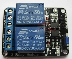
Relay details and Data Sheets
NOTE: There are family of boards with 1,2,4,or 8 relays). (SEE Them HERE))
NOTE: The relays used are made by SONGLE and the specification sheets are here:
Media:SRD-05VDC-SL-C-Datasheet.pdf
The 30A version SONGLE relay is shown here:
Media:SLA-05VDC-SL-C_Datasheet.pdf
There are both Optically-isolated relays (recommended for most applications) and non-isolated versions. It has the same relay as the Electronic Brick 1-relay board and basically the same transistor drive circuitry. You would connect Arduino to the connector on the upper left. +5V to VCC, four input pins, and GND.
NOTE: A difference is that these control pins are Active LOW which means the relay turns on when you set the Arduino output to LOW. You can wire the relay outputs to various devices rated at up to 10 Amps. The connections on the far right have a diagram similar to that shown above. There are LEDs on the board that show when a relay is active, and a green LED to show that +5V power is applied. Notice how our multicolor flat cable and Sensor Shield makes this easy to connect!
And the YourDuino RoboRED microcomputer board has those connectors built in.
Optically-Isolated Relays

Here is an optically-isolated 8-relay board. (Available HERE)
It has an added feature of Optical Isolation. This means that all Arduino really does is turn on an LED inside an IC package, and THAT turns the relay on. So there does not need to be any direct connection between Arduino and the relay driver circuits. This can be an advantage and safety factor when controlling a separate piece of equipment that has it's own power supplies and perhaps a metal case etc. (2 and 4 Relay Boards are also available). The 8-relay board shown here gives you a choice of powering the relay drive circuits from the same supply as Arduino, or isolating Arduino by removing the jumper over at the right. In that case you need to have some separate +5V supply connected to GND and the "JD-VCC" pin (whatever THAT label means...). Here's a closeup look at the pins:

If you isolate Arduino, you need to connect +5V ONLY (NOT GND) from Arduino to the VCC pin. The Arduino output pins go to IN1 through IN8. And again, these pins are Active LOW. NOTE: Some relay boards have 2 GND pins; they are connected together. The separate 5V supply would go from
- JD-VCC (Jumper removed)
- GND
The ONLY connection to Arduino would be
- Relay board VCC to Arduino +5V
- (signal pins to In0, IN1 etc)
EXAMPLE: Isolated Wiring for a 4-relay Board (Same idea for 2 or 8-relay boards)

Here's the Schematic Diagram of the Optically-Isolated Relay boards: The Ground Symbol at the bottom is labelled "GND". 
NOTE on 3.3V Signals: It is possible to use these relay boards with 3.3V signals, IF the JD-VCC(RelayPower) is provided from a +5V supply and the VCC to JD-VCC jumper is removed. . That 5V relay supply could be totally isolated from the 3.3V device, or have a common ground IF opto-isolation is not needed. If used with isolated 3.3V signals, VCC (To the input of the opto-isolators, next to the IN pins) should be connected to the 3.3V device's +3.3V supply (Or the devices 5V supply if available, like BeagleBoneBlack). You should test with your 3.3V device to be sure. We will soon be testing with Arduino DUE , BeagleBoneBlack, Intel Galileo and Raspberry Pi which are 3.3V devices. You can control a lot of different lights, water valves, and ventilation systems with relays like this. With some sensors and your Software Sketch ideas, an intelligent system may be born.
NOTE: Sometimes switching these kinds of loads can cause Electromagnetic Interference, Arduino lockup etc. More information on handling these problems http://arduinoinfo.mywikis.net/wiki/RelayIsolation is available HERE:] Comments, Critiques, Suggestions welcome! terry@yourduino.com
AC vs DC: Why do I care?
When you are switching power, you care if it is AC or DC. You care because there are different effects on the switching elements you use, which could be metal-contact relays, Power Transistors, Silicon-Controlled-Rectifiers or TRIACS.
Turning things ON:
When you make the connection to turn something on, current starts to flow. If the load is a nice pure resistance like a heater element then the current just starts up and stays the same. But if the Load is a motor or an incandescent lamp, there is a sudden inrush of current right at the beginning. Your switching device has to be able to handle that.
Turning things OFF:
This is more of a problem. When you break the connection to turn something off, bad things can happen, especially if the load is 'inductive' like a motor, a magnet, a relay coil etc. Such loads produce a sudden high voltage in the reverse direction, that can spark and damage relay contacts or internally damage transistors, SCRs, TRIACS. There are two approaches to handling this:
- Make sure the switching device is rated to handle this type of load. Notice that relays often have two ratings: A resistive load in Amps, and a Motor load in Horsepower which considers these situations.
- Use some method of suppressing the high voltage transient. Like these:
- Connect a reverse diode across magnets and relay coils.
- Connect a MOV (Metal Oxide Varistor) surge suppressor across the load.
- Connect some resistor-capacitor combination across the switching contacts
Turning Off AC vs DC:
![link=http://www.yourduino.com/sunshop/index.php?l=search_list&s[search]=ssr&s[title]=Y&s[short_desc]=Y&s[full_desc]=Y&s[sku]=Y&s[match]=all&s[cid]=0](/w/images/8/8c/SSR-25DA.jpg)
![link=http://www.yourduino.com/sunshop/index.php?l=search_list&s[search]=ssr&s[title]=Y&s[short_desc]=Y&s[full_desc]=Y&s[sku]=Y&s[match]=all&s[cid]=0](/wiki/File:SSR-25DA.jpg)
It's easier to turn off AC than DC. Why?? Because AC is constantly changing from + to - and there is an instant when the voltage is zero. A spark that started when the contact opened will usually stop when the voltage gets to zero. A DC spark / arc could continue for some time, acting like a miniature welder and welding relay contacts together. Some electronic circuits are made smart. They wait for the voltage to become Zero (The "Zero-Crossing") and then turn off. You may see references to "Zero-crossing-switches". There are Zero-Crossing Solid State Relays like this one (right) that can switch 25 to 50 amps. See it here: OK, let's do some practical DC switching before we do any more of this details stuff...
DC Switching:
DC can be switched with relays, subject to the arcing problem mentioned above. The "Starter Solenoid" Relay in your car may switch hundreds of amps at 12 volts. DC can be switched with transistors. Unless you printed this, there are millions of little DC transistor switches running in your computer right now. But let's use a big transistor and switch a big light on, as an example.
Low side vs. High side transistor switch
Why do these both exist, how do they work, and when do you use them? by James Lewis (See his links below)
[image: 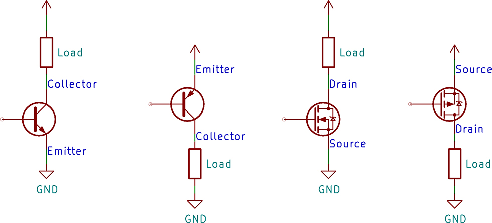 ]
]
A common task for a transistor is switching a device on and off. There are two configurations for a transistor switch: low side and high side. The location of the transistor determines the type of circuit and its name. Either transistor configuration can use a BJT or MOSFET.
See the entire article by James Lewis HERE
And here is an example using pre-built Power Field Effect Transistors:
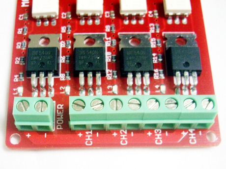
These days most power transistors are "POWER FETs" - Power Field Effect Transistors. We'll use a small board with four Power FETs that looks like this (right): (You can get one here: )
This board also has "Optical Isolation" (See above). The isolator chips are the white ones in the photo. The Power FETS are IRF540 types and have a maximum rating of 100VDC and 30 Amps (but stay below 10 Amps without heat sinks on the FETS). This is another of the "Electronic Brick" series and it's easy to connect each Power FET channel to Arduino with 3-wire cables to a "http://arduinoinfo.mywikis.net/wiki/SensorShield Sensor Shield]". Any Arduino I/O pin can drive one of these FETs.

In use, the + and - terminals are connected to the power source, such as 9 to 50 Volts DC. The loads are connected to the + and - terminals of the channel being used. This configuration is very usual and is called a "low side switch". The load is connected to the + power, and the switch connects it to GND to turn it on. In the example on the right (An older version board!), a 12V battery is the power source and a 12V cabinet light is the load. In the close up photo you can see the lamp load (white wires) is connected to + and S2.The Good Old Blink program works fine and the DC powered lamp blinks away happily.
Power_Control:Dimming/Speed

See "Motor Drivers" for more examples and reversible options.
ArduinoSoftware Sketch YourDuino PWM Power Example
/* YourDuino PWM Power Example
 "analogWrite" outputs a Pulse Width Modulated signal
 terry@yourduino.com
 Fades an LED or Lamp up and down
 NOTE: analogWrite values are from 0..255

 */

/*-----( Import needed libraries )-----*/
/*-----( Declare Constants )-----*/
#define ledPin  9    // LED connected to digital pin 9
/*-----( Declare objects )-----*/
/*-----( Declare Variables )-----*/
int fadeValue;  //Value to be sent to PWM


void setup()   /****** SETUP: RUNS ONCE ******/
{
  // (Not Used)

}//--(end setup )---


void loop()   /****** LOOP: RUNS CONSTANTLY ******/
{
  // fade up min to max
  for(fadeValue = 0 ; fadeValue <= 255; fadeValue +=5)
  {
    analogWrite(ledPin, fadeValue);
    delay(50);
  } // End Fade Up

  delay(2000); // Hold 2 seconds at max brightness

  // fade out max to min
  for(fadeValue = 255 ; fadeValue >= 0; fadeValue -=5)
  {
    analogWrite(ledPin, fadeValue);
    delay(50);
  }
  delay(2000); // Hold 2 seconds at off

}//--(end main loop )---

/*-----( Declare User-written Functions )-----*/
//None

//*********( THE END )***********
NEXT: SOLID STATE RELAYS TO CONTROL 120 or 240V AC LOADS
RE: Christmas light strings - this varies a lot with different types of incandescent (large or mini) and LED strings. Some good guidelines can be found here:
Here is an example Software Sketch for a 8-channel SSR board (Seen Here): It can be cut-pasted into an Arduino IDE window.
ArduinoSoftware Sketch YourDuino SSRPower Example
/* YourDuino Example: 8-channel Solid State Relay Board
  This board is "active high".
   terry@yourduino.com */

/*-----( Import needed libraries )-----*/
/*-----( Declare Constants )-----*/
#define RELAY_ON 1
#define RELAY_OFF 0

#define Relay_1  2  // Arduino Digital I/O pin number
#define Relay_2  3
#define Relay_3  4
#define Relay_4  5
#define Relay_5  6
#define Relay_6  7
#define Relay_7  8
#define Relay_8  9
/*-----( Declare objects )-----*/
/*-----( Declare Variables )-----*/
int waittime; // Delay between changes
void setup()   /****** SETUP: RUNS ONCE ******/
{
  waittime = 1000;
//-------( Initialize Pins so relays are inactive at reset)----
  digitalWrite(Relay_1, RELAY_OFF);
  digitalWrite(Relay_2, RELAY_OFF);
  digitalWrite(Relay_3, RELAY_OFF);
  digitalWrite(Relay_4, RELAY_OFF);
  digitalWrite(Relay_5, RELAY_OFF);
  digitalWrite(Relay_6, RELAY_OFF);
  digitalWrite(Relay_7, RELAY_OFF);
  digitalWrite(Relay_8, RELAY_OFF);


//---( THEN set pins as outputs )----
  pinMode(Relay_1, OUTPUT);
  pinMode(Relay_2, OUTPUT);
  pinMode(Relay_3, OUTPUT);
  pinMode(Relay_4, OUTPUT);
  pinMode(Relay_5, OUTPUT);
  pinMode(Relay_6, OUTPUT);
  pinMode(Relay_7, OUTPUT);
  pinMode(Relay_8, OUTPUT);
  delay(4000); //Check that all relays are inactive at Reset

}//--(end setup )---


void loop()   /****** LOOP: RUNS CONSTANTLY ******/
{
//---( Turn all 8 relays ON in sequence)---
  digitalWrite(Relay_1, RELAY_ON);// set the Relay ON
  delay(waittime);              // wait for a second
  digitalWrite(Relay_2, RELAY_ON);// set the Relay ON
  delay(waittime);              // wait for a second
  digitalWrite(Relay_3, RELAY_ON);// set the Relay ON
  delay(waittime);              // wait for a second
  digitalWrite(Relay_4, RELAY_ON);// set the Relay ON
  delay(waittime);
  digitalWrite(Relay_5, RELAY_ON);// set the Relay ON
  delay(waittime);              // wait for a second
  digitalWrite(Relay_6, RELAY_ON);// set the Relay ON
  delay(waittime);              // wait for a second
  digitalWrite(Relay_7, RELAY_ON);// set the Relay ON
  delay(waittime);              // wait for a second
  digitalWrite(Relay_8, RELAY_ON);// set the Relay ON
  delay(waittime * 4);              // wait see all relays ON

//---( Turn all 8 relays OFF in sequence)---
  digitalWrite(Relay_1, RELAY_OFF);// set the Relay OFF
  delay(waittime);              // wait for a second
  digitalWrite(Relay_2, RELAY_OFF);// set the Relay OFF
  delay(waittime);              // wait for a second
  digitalWrite(Relay_3, RELAY_OFF);// set the Relay OFF
  delay(waittime);              // wait for a second
  digitalWrite(Relay_4, RELAY_OFF);// set the Relay OFF
  delay(waittime);
  digitalWrite(Relay_5, RELAY_OFF);// set the Relay OFF
  delay(waittime);              // wait for a second
  digitalWrite(Relay_6, RELAY_OFF);// set the Relay OFF
  delay(waittime);              // wait for a second
  digitalWrite(Relay_7, RELAY_OFF);// set the Relay OFF
  delay(waittime);              // wait for a second
  digitalWrite(Relay_8, RELAY_OFF);// set the Relay OFF
  delay(waittime * 4);              // wait see all relays OFF


}//--(end main loop )---
//*********( THE END )***********
TO COME:
Some Details: POWER, Sources and Loads, Circuits etc.