ArduinoBoardDetails
(Redirected from ArduinoChipDetails)
Jump to navigation
Jump to search
ARDUINO MICROCOMPUTER BOARD and CHIP DETAILS (Schematics and Mechanical drawings below ):
- ARDUINO (UNO, Duemilanove, YourDuinoRobo1) QUICK REFERENCE: Functions of the different pins, etc.
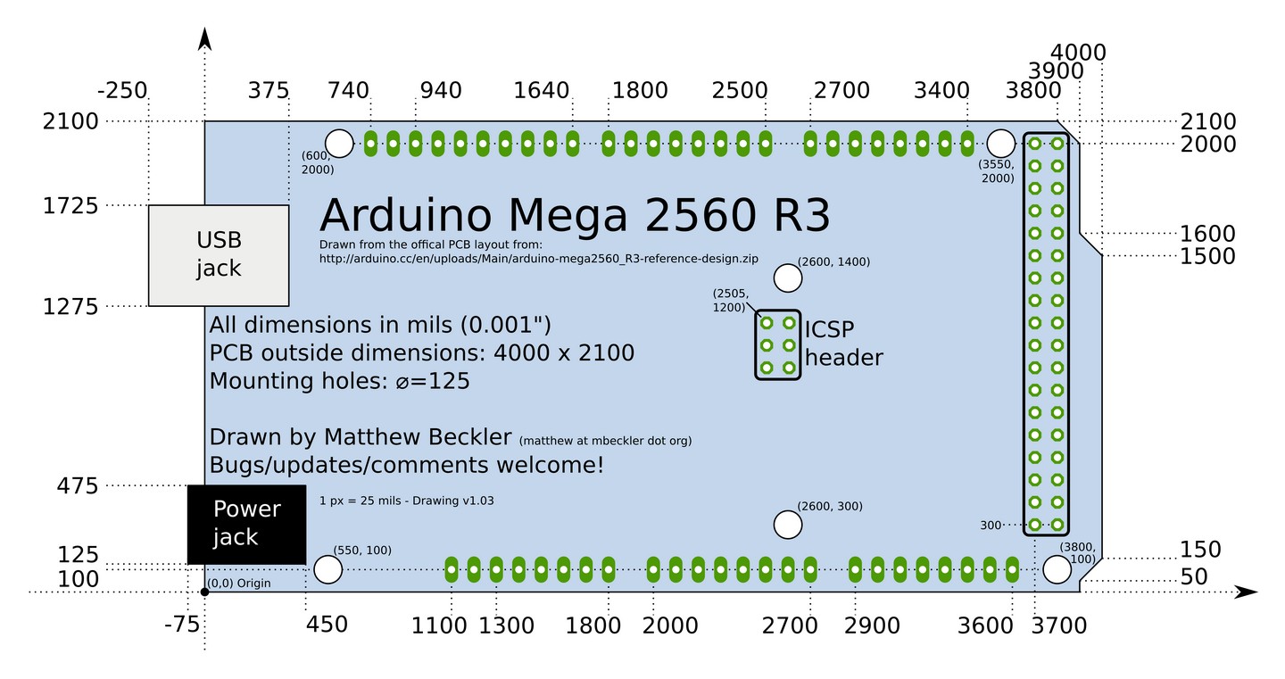
- ARDUINO (MEGA) QUICK REFERENCE: Functions of the different pins, Schematic Diagram etc.
- ARDUINO PIN CURRENT LIMITATIONS: Be Nice to your Arduino!
- ARDUINO INPUT PIN CHARACTERISTICS: What voltage is a "1"? a "0"?
- COMPARISION of the ARDUINO UNO and YourDuinoRoboRED
Details of the actual ATmega Microcontroller CHIP used in Arduino
(CLICK HERE for CHIP DETAILS):
COMPARISION OF MANY ARDUINO TYPE BOARDS
**('It's Complicated!') See section below on Power Considerations
| BOARD NAME | CHIP TYPE | SRAM | FLASH | EEPROM | SPEED | PWM | Digital | Analog In | Operating VCC | Vin Range** | 5V | 5V current mA** | 3.3V | 3.3V Current mA** | USB-CHIP | I2C | CAN | Bluetooth | Ethernet | USB-Host | SD Card |
|---|---|---|---|---|---|---|---|---|---|---|---|---|---|---|---|---|---|---|---|---|---|
| Duemilanove 328 (Older) | ATmega328 | 2K | 32k | 1k | 16MHz | 6 | 14 | 6 | 5V | 7-12V | Yes | Yes | 50 | FTDI FT232RL | 1 | No | No | No | No | No | |
| Arduino Uno (R3) | ATmega328 | 2k | 32k | 1k | 16MHz | 6 | 14 | 6 | 5V | 7-12V | Yes | Yes | 50 | ATmega16U2 | 1 | No | No | No | No | No | |
| RoboRED (Yourduino) | ATmega328 | 2k | 32k | 1k | 16MHz | 6 | 14 | 6 | 5V/3.3V | 7-23V | Yes | 2000 | Yes | 500 | ATmega16U2 | 1 | No | No | No | No | No |
| Sparkfun RedBoard | ATmega328 | 2k | 32k | 1k | 16MHz | 6 | 14 | 6 | 5V | 7-23V | Yes | Yes | 50 | FTDI FT232RL | 1 | No | No | No | No | No | |
| Arduino Nano 3.0 | ATmega328 | 2k | 32k | 1k | 16MHz | 6 | 14 | 8 | 5 | 7-12V | Yes | Yes | 50 | FTDI FT232RL | 1 | No | No | No | No | No | |
| Arduino Mega 2560 | ATmega2560 | 8k | 256k | 4k | 16MHz | 14 | 54 | 16 | 5V | 7-18V | Yes | Yes | 50 | ATmega16U2 | 1 | No | No | No | No | No | |
| Leonardo | ATmega32U4 | 2.5k | 32k | 1k | 16MHz | 7 | 25 | 12 | 5V | 3.3V-5V | VCC | VCC | 50 | Built-In | 1 | No | No | No | No | No | |
| Arduino Micro | ATmega32u4 | 2.5k | 32k | 1k | 16MHz | 7 | 25 | 12 | 5V | 3.3V-5V | VCC | VCC | ? | Built-In | 1 | No | No | No | No | No | |
| Arduino Due | SAM3X8E | 96kb | 512kb | N/A | 84MHz | 12 | 70 | 12 | 3.3V | 7-12V | No | VCC | ? | Built-In | 2 | Yes | No | No | Yes | No | |
| Arduino Ethernet | ATmega328 | 2k | 32k | 1k | 16MHz | 4 | 9 | 6 | 5 | 6-18V | Yes | Yes | ? | EXTERNAL | 1 | No | No | W5100 | No | No | |
| Arduino Pro Mini 328 5V | ATmega328 | 2k | 32k | 1k | 16MHz | 6 | 14 | 6 | 5V | 5-12V | Yes | ? | No | EXTERNAL | 1 | No | No | No | No | No | |
| Arduino Mini | ATmega328 | 2k | 32k | 1k | 16MHz | 6 | 14 | 8 | 5 | 7V-9V | Yes | No | ? | EXTERNAL | 1 | No | No | No | No | No | |
| Arduino Pro 3.3V | ATmega328 | 2k | 32k | 1k | 8MHz | 6 | 14 | 6 | 3.3V | 3.35-12V | No | ? | Yes | EXTERNAL | 1 | No | No | No | No | No | |
| Arduino Pro 5V | ATmega328 | 2k | 32k | 1k | 16MHz | 6 | 14 | 6 | 5V | 5-12V | Yes | No | EXTERNAL | 1 | No | No | No | No | No | ||
| LilyPad 328 Main Board | ATmega328 | 2k | 32k | 1k | 8MHz | 6 | 14 | 6 | 2.7-5.5V | N/A | N/A | EXTERNAL | 1 | No | No | No | No | No | |||
| Seeeduino | ATmega328 | 2k | 32k | 1k | 16MHz | 6 | 14 | 6 | 5V | 3.3V-12V | VCC | Yes | FTDI FT232RL | 1 | No | No | No | No | No | ||
| Seeeduino Ethernet | ATmega328 | 2k | 32k | 1k | 16MHz | 6 | 14 | 6 | 5V | 3.3V-12V | VCC | Yes | EXTERNAL | 1 | No | No | W5100 | No | Yes | ||
| Seeeduino Stalker V2.0 | ATmega328 | 2k | 32k | 1k | 16MHz | 6 | 14 | 6 | 5V | 3.3V-5V | VCC | ? | EXTERNAL | 1 | No | No | No | No | microSD | ||
| Teensyduino | ATmega32U4 | 2.5k | 32k | 1k | 16MHz | 7 | 25 | 12 | 5V | 3.3V-5V | VCC | VCC | Built-In | 1 | No | No | No | No | No |
Power Considerations:
- VIN. The input voltage to the Arduino board when it's using an external power source (as opposed to 5 volts from the USB connection or other regulated power source). This is connected to the center terminal of the Coaxial "Power" connector through a "M7" 1A silicon diode (protection against reverse applied voltage). You can supply a voltage through this pin, or, if supplying voltage via the power connector, access it through this pin. The current that can be drawn from the Vin pin is limited by the diode and trace width. The diode is rated at 1 amp and the board traces can't handle much above 2 amp. Because of the diode, the voltage at Vin will be .7 to .9 volts less than the voltage supplied on the external power connector.
- 5V.The regulated power supply used to power the microcontroller and other components on the board. This can come either from VIN/Power Connctor via an on-board regulator, or be supplied by USB or another regulated 5V supply.
- LIMITATIONS: If an external power supply is connected to VIN, the current available from 5V depends on the power dissipated in the onboard regulator, which is a maximum of about 1.5W. (Ref )At 7V VIN this is about 700mA, at 9V VIN it's about 350 mA , at 12V it's about 200 mA. Calculate: I=P/E so available current at 5V = 1.5 / (VIN - 5)
- PRACTICAL LIMITS: The ATMEGA328 and other chips use about 120mA, so what's LEFT for your LED's , and other external devices is the limitations above minus about 150 mA, so now at VIN of: 7V it's about 550mA, 9V about 200 mA, and 12V 50 mA.
- NOTE: The YourDuino RoboRED has a totally different 5 V regulator, a switch-mode system that provides up to 2 amps (2000 mA).
- 3V3.A 3.3 volt supply generated by the on-board regulator or FTDI chip. Maximum current draw is 50 mA.
- NOTE: The YourDuinoRobo1 and YourDuino RoboRED have a separate 3.3V power regulator that provides up to 350mA at 3.3V
- GND. Ground pins.
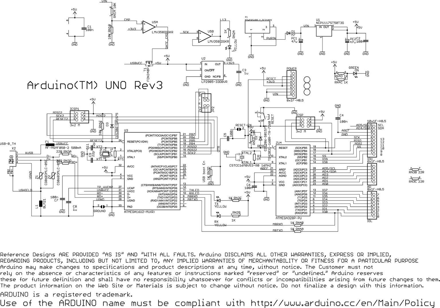
Schematic diagram of the Arduino UNO
DOWNLOAD The ATMEL Datasheet for the ATmega328 chip used in the UNO, RoboRED and NANO
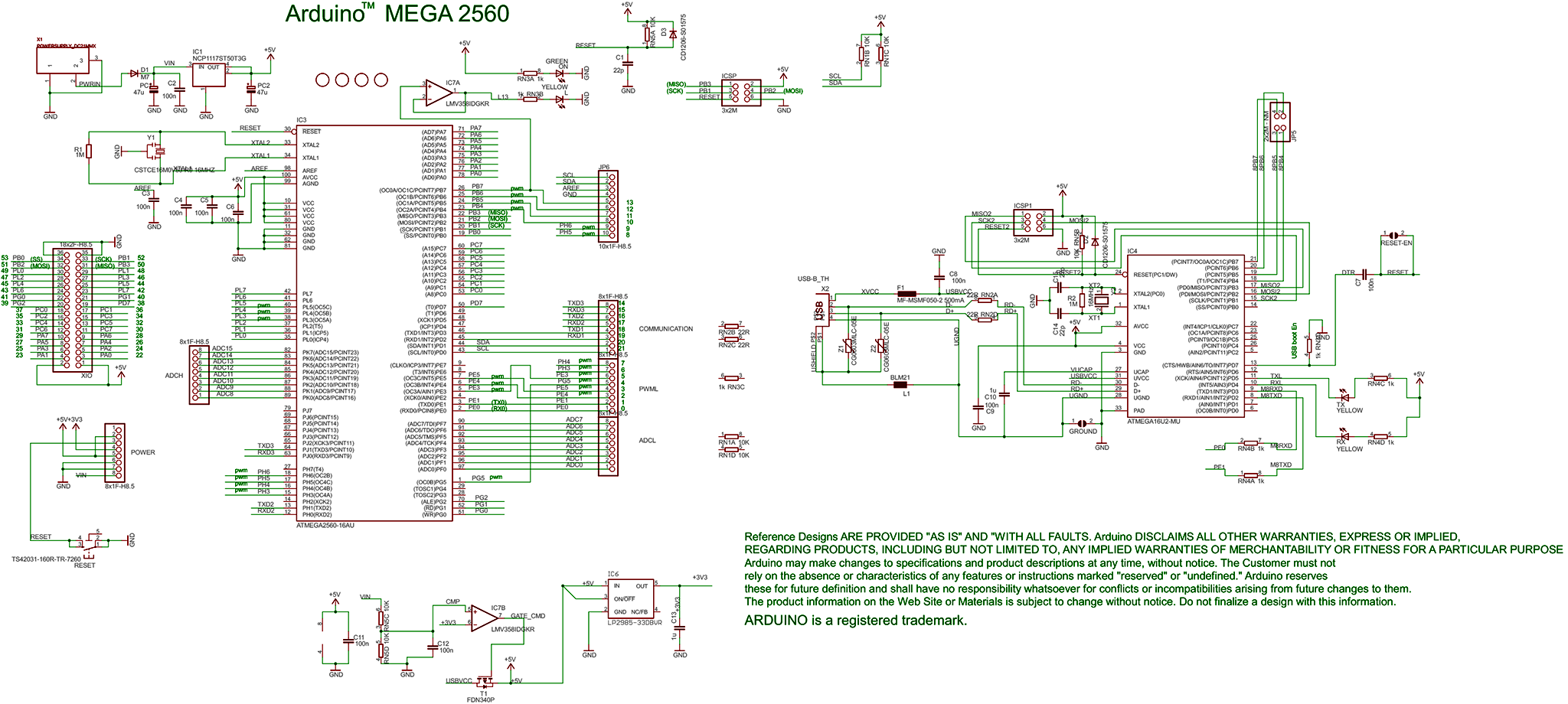
Schematic diagram of the Arduino MEGA
DOWNLOAD The ATMEL Datasheet for the ATmega2560 chip used in the MEGA
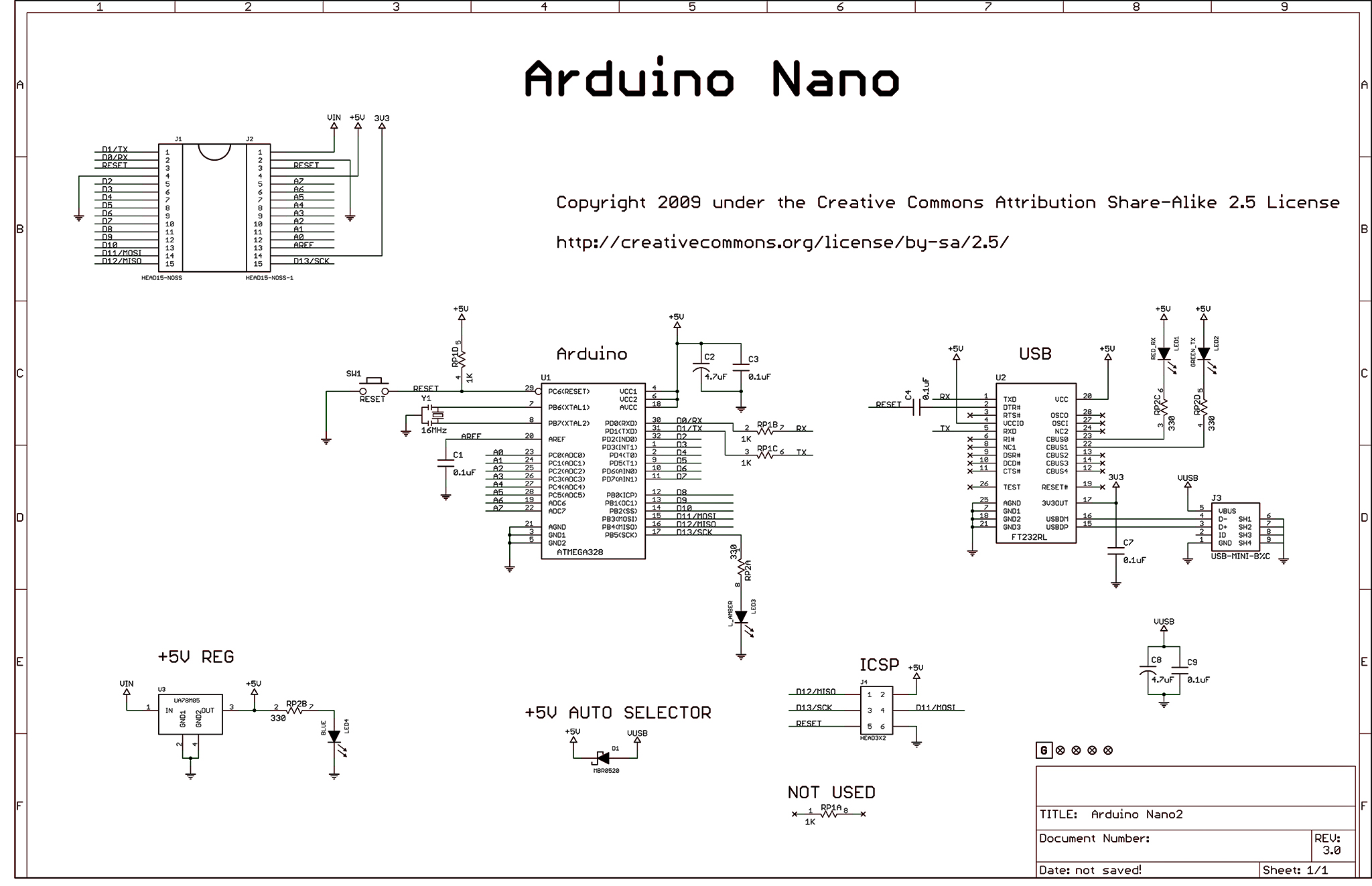
Schematic diagram of the Arduino NANO
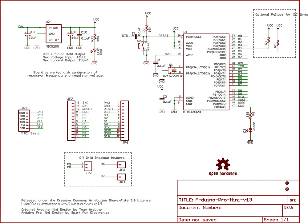
Schematic diagram of the Arduino Pro Mini
ARDUINO/YOURDUINO BOARD DIMENSIONS:
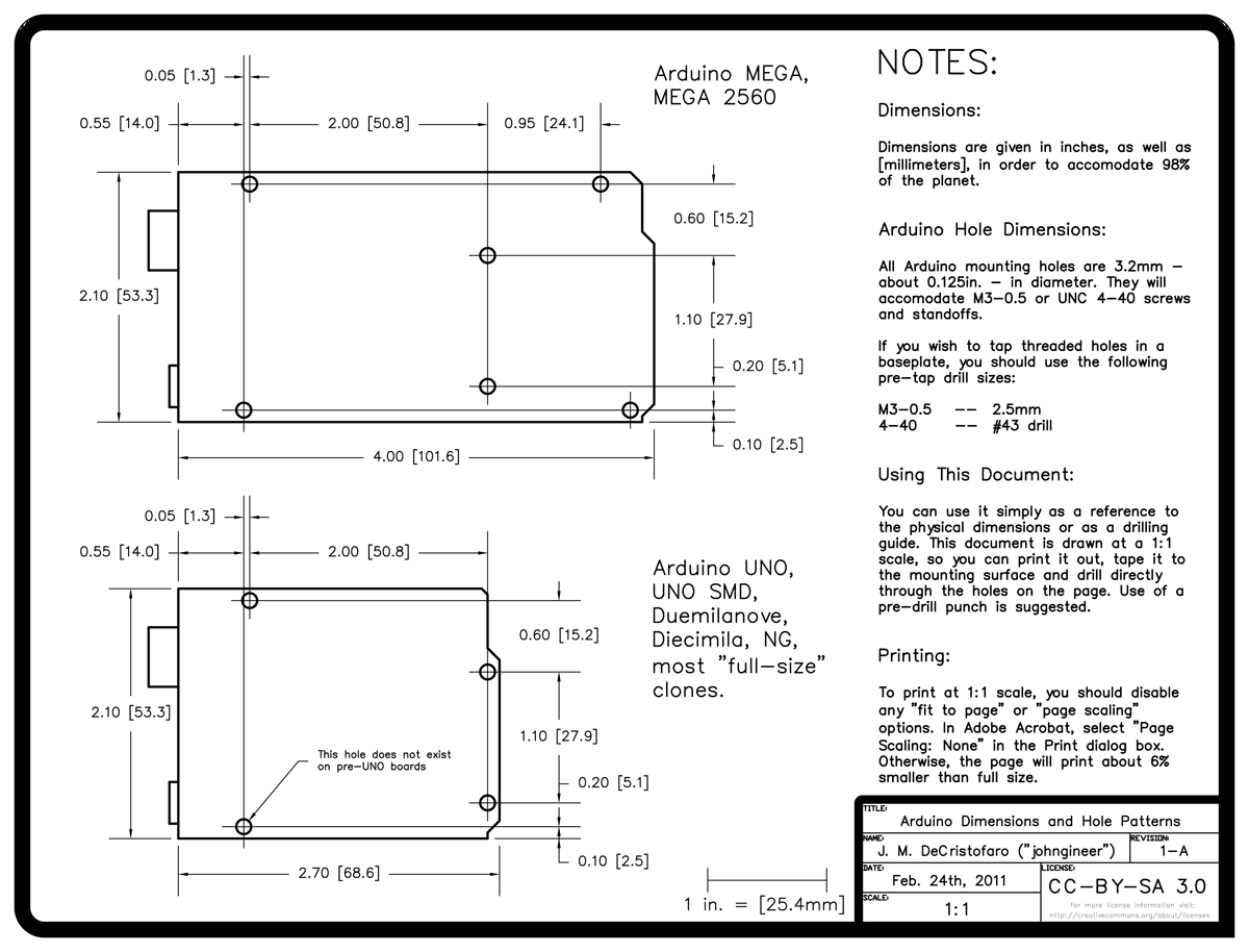
NOTE: YourDuinoRoboRED also does not have the lower-left hole.
