QuickRef
Detailed comparision of Arduino UNO and YourDuino RoboRED
Official DataSheet for ATmega328P (UNO, RoboRED etc.) : File:Atmel-42735-8-bit-AVR-Microcontroller-ATmega328-328P Datasheet.pdf
Official DataSheet for ATmega1280/2560 (MEGA etc.) : File:Atmel-2549-8-bit-AVR-Microcontroller-ATmega640-1280-1281-2560-2561 datasheet.pdf
Arduino Input Pin Characteristics:
Arduino Output Pin Limitations:
Arduino Duemilanove / YourDuino328 / YourDuino RoboRED / YourDuinoRobo1:
Input and Output
Each of the 14 digital pins can be used as an input or output, using pinMode(), digitalWrite(), and digitalRead() functions. They operate at 5 volts. Each pin can provide (Source) or receive (Sink) a maximum of 40 mA (20 mA is recommended maximum for normal designs) and has an internal pull-up resistor (that can be activated when desired) of 20-50 kOhms.
Details on allowable pin current HERE(click)
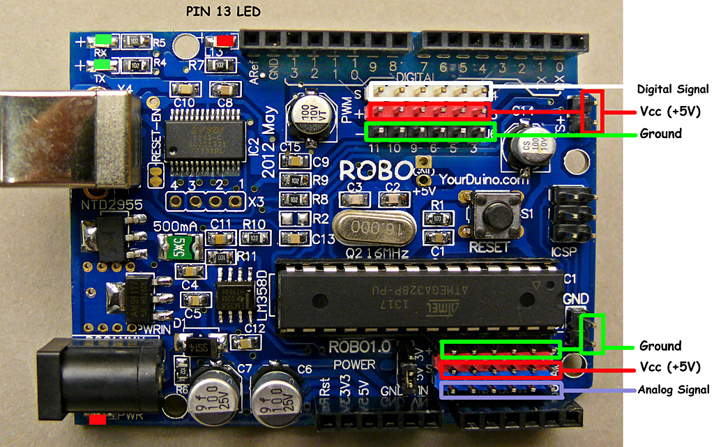
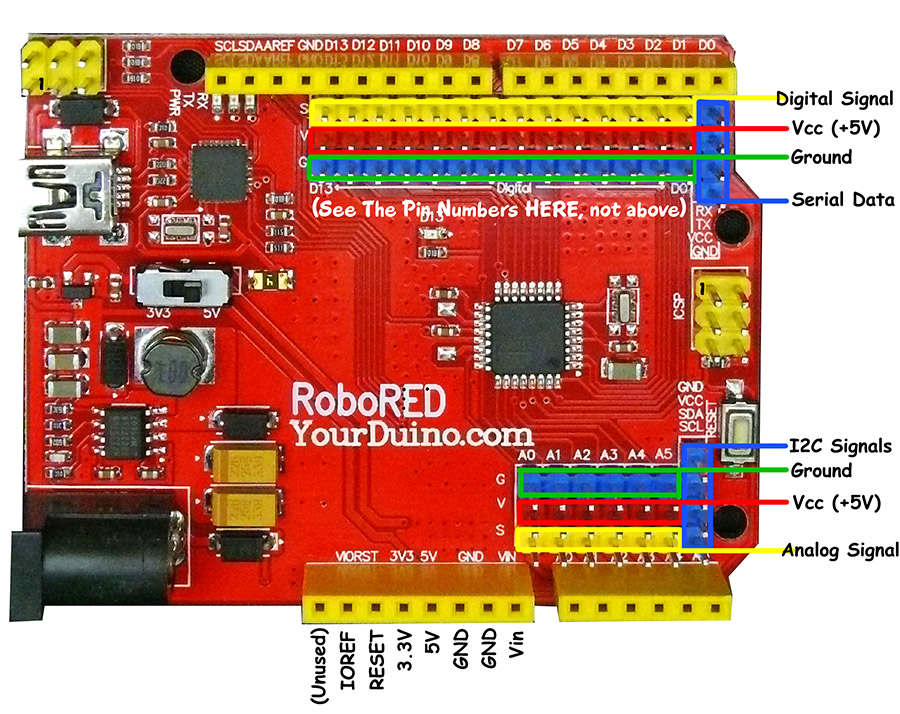
NOTE: The YourDuino RoboRED has the same pins, but they are additionally connected to 3-pin connectors with Ground-Voltage-Signal. See Pins and Cables HERE:
Specialized Pin Functions:
- Serial: 0 (RX) and 1 (TX). Used to receive (RX) and transmit (TX) TTL serial data. These are used for downloading of software sketches and should be reserved for that in most designs. These pins are connected to the corresponding pins of the ATmega8U2 (UNO versions) or FTDI USB-to-TTL Serial chip.
- External Interrupts: 2 and 3. These pins can be configured to trigger an interrupt on a low value, a rising or falling edge, or a change in value. See the attachInterrupt() function for details.
- PWM: 3, 5, 6, 9, 10, and 11. Provide 8-bit PWM output with the analogWrite() function.
- SPI: 10 (SS), 11 (MOSI), 12 (MISO), 13 (SCK). These pins support SPI communication using the SPI library.
- LED: 13. There is a built-in LED connected to digital pin 13. When the pin is HIGH value, the LED is on, when the pin is LOW, it's off.
There are 6 analog inputs, labeled A0 through A5, each of which provide 10 bits of resolution (i.e. 1024 different values). By default they measure from ground to 5 volts, though is it possible to change the upper end of their range using the AREF pin and the analogReference() function.
NOTE: The Analog input pins can also be used as Digital Input or Output pins.
Additionally, some pins have specialized functionality:
- I2C aka TWI: (A4 or SDA pin) and (A5 or SCL pin). Support I2C -TWI (Two Wire Interface) communication using the Wire library.
There are a couple of other pins on the board:
- AREF. Reference voltage for the analog inputs. Used with analogReference().
- Reset. Bring this line to Ground (LOW) to reset the microcontroller. Typically used to add a reset button to shields which block the one on the board.
Power Considerations: (See "Detailed Power Considerations", below)
The power pins are as follows:
- VIN. The input voltage to the Arduino board when it's using an external power source (as opposed to 5 volts from the USB connection or other regulated power source). This is connected to the center terminal of the Coaxial "Power" connector through a "M7" 1A silicon diode (protection against reverse applied voltage). You can supply a voltage through this pin, or, if supplying voltage via the power connector, access it through this pin. The current that can be drawn from the Vin pin is limited by the diode and trace width. The diode is rated at 1 amp and the board traces can't handle much above 2 amp. Because of the diode, the voltage at Vin will be .7 to .9 volts less than the voltage supplied on the external power connector.
- 5V.The regulated power supply used to power the microcontroller and other components on the board. This can come either from VIN/Power Connctor via an on-board regulator, or be supplied by USB or another regulated 5V supply.
- LIMITATIONS: If an external power supply is connected to VIN, the current available from 5V depends on the power dissipated in the onboard regulator, which is a maximum of about 1.5W. (Ref )At 7V VIN this is about 700mA, at 9V VIN it's about 350 mA , at 12V it's about 200 mA. Calculate: I=P/E so available current at 5V = 1.5 / (VIN - 5)
- PRACTICAL LIMITS: The ATMEGA328 and other chips use about 120mA, so what's LEFT for your LED's , and other external devices is the limitations above minus about 150 mA, so now at VIN of: 7V it's about 550mA, 9V about 200 mA, and 12V 50 mA.
- NOTE: The YourDuino RoboRED has a totally different 5 V regulator, a switch-mode system that provides up to 2 amps (2000 mA).
- 3V3.A 3.3 volt supply generated by the on-board regulator or FTDI chip. Maximum current draw is 50 mA.
- NOTE: The YourDuinoRobo1 and YourDuino RoboRED have a separate 3.3V power regulator that provides up to 350mA at 3.3V
- GND. Ground pins.
Memory:
The ATmega328 has 32 KB of Flash Memory for user's Software Sketches (with 0.5 KB used for the bootloader). It also has 2 KB of SRAM and 1 KB of EEPROM (which can be read and written with the EEPROM library).
Summary:
| Microcontroller |
ATmega328 |
| Operating Voltage |
5V |
| Input Voltage (recommended) |
7-12V |
| Input Voltage (limits) |
6-20V |
| Digital I/O Pins |
14 (of which 6 provide PWM output) |
| Analog Input Pins |
6 |
| DC Current per I/O Pin |
40 mA |
| DC Current for 3.3V Pin |
50 mA |
| Flash Memory |
32 KB (ATmega328) of which 0.5 KB used by bootloader |
| SRAM |
2 KB (ATmega328) |
| EEPROM |
1 KB (ATmega328) |
| Clock Speed |
16 MHz |
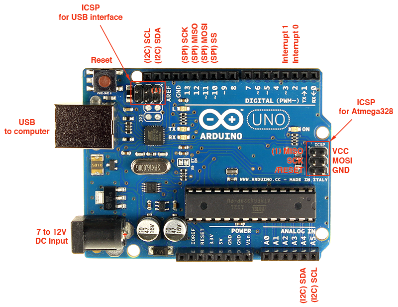
ARDUINO UNO BOARD LAYOUT:
From Nick Gammon (Original Info HERE)
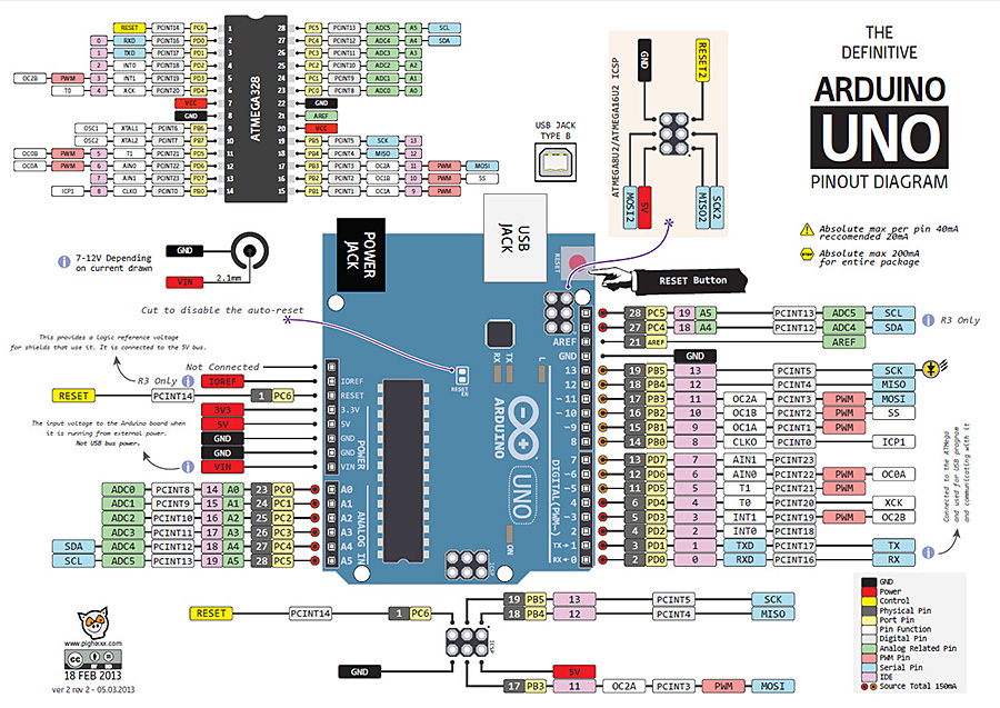
ARDUINO UNO BOARD LAYOUT DIAGRAM: THANKS! to Alberto Piganti (Original PDF HERE)
YourDuinoROBO1 BOARD LAYOUT DIAGRAM:
YourDuino RoboRED BOARD LAYOUT DIAGRAM:
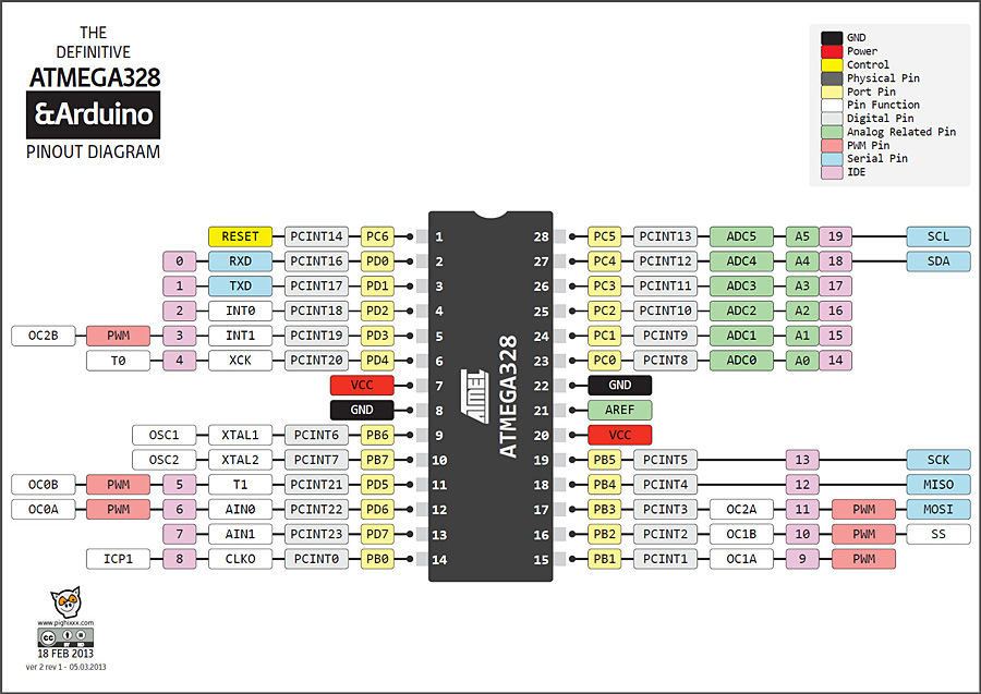
ATMEGA328 (UNO, Duemilanove) CHIP PINOUT DIAGRAM:
DETAILED_POWER_CONSIDERATIONS:
(Credits: www.thebox.myzen.co.uk/Tutorial/Power_Examples Sorry - Now unreachable)
Powering an Arduino
The Arduino UNO has an on board regulator for use when powering from an external power supply. It uses the MC33269 series regulator chip. A question often asked is “can I run it off a 12V supply”. A look at the schematics show that C5 and C6 will be exposed to the full input voltage so the first thing is to see that those capacitors are rated at at least 12V, in this case they are with a 35V rating. So no trouble there. Next see if the regulator can stand that much, again looking at the data sheet shows this to be able to stand 20V. So next see if it can handle the power.
The regulator drops the difference between the input voltage and the output voltage. Also their is a series diode in front of the regulator so that drops 0.7V. This gives us a total voltage drop across the regulator of 12 - 5 - 0.7 = 6.3V.
The power burnt off by the regulator is a function of the current it is taking. Now the board takes about 120mA when it is running, add a bit extra for interface current LEDs and so on and let’s call that 200mA.
So now we can calculate the power, it is simply 6.3 * 0.2 = 1.26 Watts.
Is that too much? Well the data sheet for that device is a little more helpful than most. In includes this graph which shows what effect the copper on the PCB has on the thermal resistance.
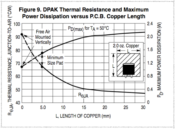
If you look at the Arduino you will see that there is only the minimum pad, that is there is no extra copper surrounding the regulator. So in this case reading off the graph we have a maximum power of about 1.5W for a 50 oC ambient or a thermal resistance of 68 oC / W. So that means for our example we can only draw 1.5 / 6.3 = 0.238 A or 238mA. So it looks like we will be just about OK with 200mA. The data sheet also says there is a thermal cut out that operates at 170 oC so you can use that if you need in your calculations. However, it warns that the thermal cut out is not a substitute for an adequate heat sink.
Other good Power Ideas: YourDuino RoboRED
Our friend at the company that we worked with for the YourDuino RoboRED board did a very nice design that replaces the Linear voltage regulator on usual UNOs and MEGAs with a SwitchMode Power Supply. It is both much more efficient (less power and heat wasted) and much more powerful: 10 times as much as the usual Arduino regulator: 2 AMPS (2000 mA).
Details:
- Advanced Power for your designs with new onboard 5.0V and 3.3V power supplies.
- Earlier Arduino versions had only 50 mA of current available at 3.3V but now RoboRED provides up to 500 mA at 3.3V
- An advanced 5.0V switch-mode power supply onboard the RoboRED provides MUCH more 5V power than the original: up to 2 Amps (2000 mA) to power many servos or Relay Boards or powerful LEDs, etc. And the Input Voltage rating is higher at 7-23V.
See the RoboRED board details HERE and a comparison of UNO, Robo1 and RoboRED HERE
