Brick-Generic-Sensor-Analog-Digital
Jump to navigation
Jump to search

Brick-Generic-Sensor-Analog-Digital
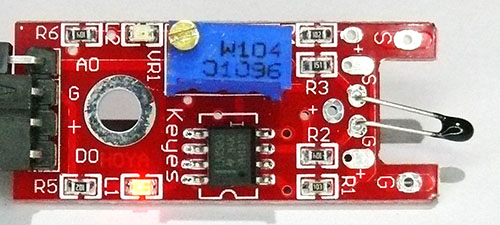
There are 7 bricks in the set that use the same circuit board with different sensors attached to the input.
  The photo on the right shows a 10K Thermistor attached to the input of the brick circuit. The schematic diagram of these Brick circuit boards is belowhttp://arduino-info.wikispaces.com   http://arduinoinfo.mywikis.net/wikiBrick-Generic-Sensor-Analog-Digital#sd  (click)]. Here are links to the specific pages for the individual sensor versions:
- Thermistor Analog + Digital Electronic Temperature Sensor
- Flame (Infrared Light) Sensor
- Sensitive Microphone Sound Sensor
- Small Microphone Sound Sensor
- Analog + Digital “Hall Effect” Magnetic Sensor
- Conductive Touch Sensor
- Magnetic Reed Switch
Here is a generic test sketch for these Electronic Bricks:
/* YourDuino.com Electronic Bricks Set - Analog-Digital All
See it here: http://yourduino.com/sunshop2/index.php?l=product_detail&p=364
Starter Example: Sketch Template
 - ELECTRONIC BRICK: The often-used Red brick with a 393 and both digital and analog outputs.
 - SEE the comments after "//" on each line below
 - CONNECTIONS:
   -
   -
 - V1.00 03/15/2015
   Questions: terry@yourduino.com */

/*-----( Import needed libraries )-----*/
//NONE YET
/*-----( Declare Constants and Pin Numbers )-----*/
#define LED_PIN 13          // define on-board LED
#define DIGITAL_IN_PIN  3   // define the digital input pin
#define ANALOG_IN_PIN   A0  // define the analog input pin

/*-----( Declare objects )-----*/
//NONE YET

/*-----( Declare Variables )-----*/
int digitalValue ;  // read digital value
float sensorValue;  // read analoog value

void setup()   /****** SETUP: RUNS ONCE ******/
{
  pinMode (LED_PIN, OUTPUT) ;      // Onboard LED
  pinMode (DIGITAL_IN_PIN, INPUT) ;// digital input signal (Not actually required; INPUT is default)
  pinMode (ANALOG_IN_PIN, INPUT)  ;// analog  input signal (Not actually required; INPUT is default)
  Serial.begin(9600);              // Start the Serial Monitor connection
}//--(end setup )---


void loop()   /****** LOOP: RUNS CONSTANTLY ******/
{
  sensorValue = analogRead(ANALOG_IN_PIN);
  Serial.print("Analog value = ");
  Serial.print(sensorValue), DEC; // display analog value

  digitalValue = digitalRead (DIGITAL_IN_PIN) ;
  Serial.print("   Digital value = ");
  Serial.println(digitalValue), DEC; // display digital value
  if (digitalValue == HIGH) // When the sensor value exceeds the set point, LED flashes
  {
    digitalWrite (LED_PIN, HIGH);
  }
  else
  {
    digitalWrite (LED_PIN, LOW);
  }
  delay(1000);

}//--(end main loop )---

/*-----( Declare User-written Functions )-----*/


//*********( THE END )***********
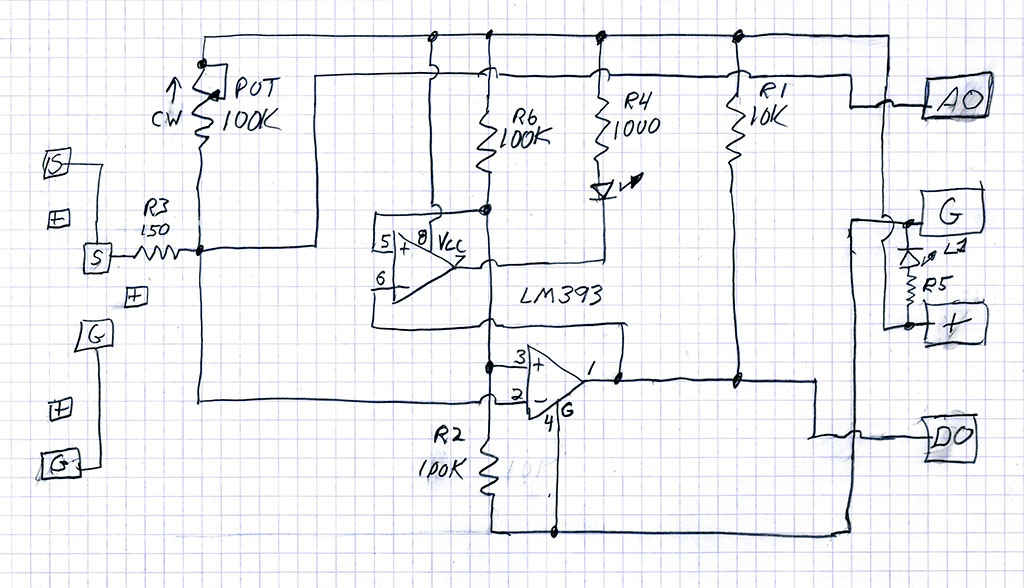
SCHEMATIC DIAGRAM:
This Electronic Brick uses an LM393 Dual Comparator chip. Sensors are connected between S and G on the input on the left of the schematic diagram. The 100K potentiometer sets the correct bias range for the device. Devices that require +5V can connect to the (+) connections. The comparator is biased at 1/2 the supply voltage by R6 and R2. When the sensor threshold value is reached the comparator output at DO (Digital Output) goes HIGH (to +5V) and this causes the upper comparator to turn on the LED. The analog voltage value at the Sensor input is also connected to the AO (Analog Output) pin where it may be measured by an Arduino analog input.