Brick-Potentiometer-Joystick
 Potentiometers and Joysticks:

Potentiometers (Often known as Pots) are human interface Input Devices. Your hand moves a knob and this changes the electrical property of the pot. Below there are examples with software to try out each kind of pot/joystick. One example controls 2 servos with a joystick.
NOTE: Not all the examples on this page go with a particular Yourduino set.
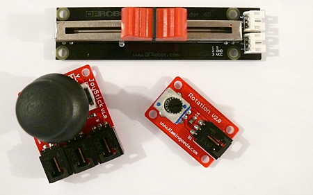
In the above photo there are 3 kinds of pots that are controlled by different hand movements: On the top is a Slide Pot, on the right is a Rotary Knob Pot and on the left is a Joystick, which is really 2 pots that you can move in X and Y directions.
NOTE: http://arduino-info.wikispaces.com http://arduinoinfo.mywikis.net/wikiBrick-Potentiometer-Joystick#jp (Click Here)] for Joystick control of colorful graphics on the PC or MAC
Pots are Voltage Dividers that can be used to send information to Arduino by connecting them to an Arduino Analog Input. We will define these things better soon.

Now let's figure out this Voltage Divider stuff. Look at the diagram on the right. A Voltage Divider has 2 resistors connected in Series, connected to a source of (V)oltage and a (G)round or common point. The connection in the middle between the two resistors is the (S)ignal Output, and is some fraction of the Input Voltage. So we can connect a pot used as a Voltage Divider to one of our 3-wire cables that have (G)(V)(S) connections as marked on the Yourduino RoboRED, for example. As we move the pot, the output voltage going to Arduino varies from 0 to 5 Volts and all the values in between.
Let's look "inside" the Rotary and Slide (Linear) pots in the photo above:


In both cases, inside there is a Resistive Strip of some material like carbon. The two ends of the strip connect to (V)oltage and (G)nd. The Wiper is moved along the strip when you move the knob on the pot. So you can change the voltage divider action, and send different voltages out the Wiper to (S)ignal to an Arduino Analog Input. Arduino can read and report that Voltage, and tell where you moved the knob to. So your human movement becomes a value known to Arduino.
For a LOT more about "Pots", see "The Secret Life of Pots" by R.G. Keen
HERE
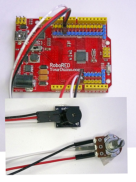 SINGLE POT EXAMPLE: (See Photo at right)

Let's hook up a pot, run some simple Software Sketch and see it work. Plug things together like this:
- The Buzzer brick and cable to I/O #10
- A Rotary Potentiometer (or Slide Pot) to Analog A0 (the first one)
- (We will also use the built-in LED on the MicroComputer board)
CONNECTIONS:
- The 3-pin "Flat-to-Latch cable is used for the Buzzer Brick. Make sure the colors go as shown. On the RoboRED, black goes to the blue pin.
- The 3-pin "Flat-to-Separate: cable is used for the potentiometer. Note the colors. The separate cable ends need to be oriented correctly: one way is loose, the other is tight. On the RoboRED black goes to the blue pin.
Set the pot turned "down", then start the Arduino IDE and get a new blank window. Copy and paste this Software Sketch:
/* YourDuino Electronic Brick Test
   Analog Potentiometers
   Flash LED speed from pot position. Faster if turned clockwise.
   Audible Alarm if TOO fast :-)
   terry@yourduino.com */


/*-----( Declare Constants )-----*/
#define POT_PIN    A0
#define LED_PIN    13  // Built-In LED
#define BUZZER_PIN 10

/*-----( Declare Variables )-----*/

int pot_value;      /* The value read from the voltage divider potentiometer */

void setup()   /*----( SETUP: RUNS ONCE )----*/
{
  pinMode(LED_PIN, OUTPUT);
  pinMode(BUZZER_PIN, OUTPUT);

}/*--(end setup )---*/


void loop()   /*----( LOOP: RUNS CONSTANTLY )----*/
{
  // read the value from the sensor(subtract from 1023 so clockwise=Brighter)
  pot_value = 1023 - analogRead(POT_PIN);

  // turn the ledPin on
  digitalWrite(LED_PIN, HIGH);

  // Wait to view the LED ON, depending on Pot position:
  delay(pot_value);

  // turn the ledPin off:
  digitalWrite(LED_PIN, LOW);

  //  Wait to view the LED OFF, depending on Pot position:
  delay(pot_value);

  //If going REALLY fast, set off the audible alarm
  if   (pot_value < 50) { digitalWrite(BUZZER_PIN, HIGH);}
                   else { digitalWrite(BUZZER_PIN, LOW); }

}/* --(end main loop )-- */

/* ( THE END ) */
Click Verify to make sure it's OK, then Upload. You should soon see "Done Uploading". If errors, check your Board and Com Port in Tools. Disconnect and reconnect the USB cable.
You should see the LED start blinking slowly. Pretend you're driving through one of those tunnels with the lights on the side. Flash. Flash, Flash. Start turning the pot up (or push the slide pot forward). The flashing gets faster and faster. Go faster, until those lights almost become a blur. Your Overspeed Alarm goes off!
There is also a "Demo of Arduino Potentiometer Rotation to Graphics Display on PC" which you can see on this page. You'll have to download the free "Processing" graphics language to run this.

JOYSTICK TO SERIAL MONITOR EXAMPLE (See Photo, right):
OK, next we'll look at the Joystick. The joystick is really two potentiometers that are linked to the handle which you can move in X and Y directions.. There is also a switch activated by pushing the knob down.
Here on the right is a Joystick connected with 3-wire cables to a http://arduino-info.wikispaces.com http://arduinoinfo.mywikis.net/wikiSensorShield Sensor Shield] on top of an Arduino. This is the easy way to get reliable connections. The Joystick X and Y outputs are connected to Arduino Analog Inputs 0 and 1. (Lots of computer stuff starts counting at Zero. Like the 14 Arduino Digital I/O ports are numbered 0 to 13.)
Let's test the Joystick. Here's what we need to do:
- Strip off a 5-wire section of the flat cable (Use brown-red-orange-yellow-green)
- Connect to the joystick as shown on right (brown at top)
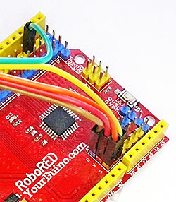
- Look closely at the joystick. Brown to GND, Red to +5V, Orange to VRx, Yellow to VRy, Green to SW
- Connect the other end as in the smaller photo: Brown to A0 G, Red to A0 V, Orange to A0 S,Yellow to A1 S, Green to D2 S

Now, start a new blank window in the Arduino IDE, and copy and paste this Software Sketch:
/* YourDuino Electronic Brick Test
 YD_Joystick  V1.02
 Reads analog voltage values from X and Y Joystick potentiometers
 "reverses" Y values so that with cable to the left, Y=0 when knob is closest
 Reads digital value from the push-knob-down switch
 Displays values on the Serial Monitor (see: https://arduinoinfo.mywikis.net/wiki/YourDuino-Serial-Monitor )
 Can also display colorful ellipse on the PC using Processing and "YD_Joystick_To_Ellipse"
 See: https://arduinoinfo.mywikis.net/wiki/Brick-Potentiometer-Joystick
 terry@yourduino.com */

/*-----( Declare Constants )-----*/
/*-----( Define Pin Numbers )-----*/
#define X_AXIS_PIN    A0  /*----(Joystick Pin connections)----*/
#define Y_AXIS_PIN    A1
#define Z_SWITCH_PIN  2

#define LED_PIN13    13  /* The on-board Pin 13 LED  */

/*-----( Declare Variables )-----*/

int  Xvalue; /*----(Values we will read from the Joystick)----*/
int  Yvalue;
int  Zvalue;

void setup()   /*----( SETUP: RUNS ONCE )----*/
{
  Serial.begin(9600);  /*----(Set up Serial Monitor Output)----*/
  Serial.println("YourDuino Joystick Test 1.02 - - 03/23/2015 -");
    Serial.println("Hold Joystick with cable to the left .");
  pinMode(LED_PIN13, OUTPUT); // Set the mode of these pins
  pinMode(Z_SWITCH_PIN, INPUT_PULLUP); // Use built-in pullup resistor

}/*--(end setup )---*/


void loop()   /*----( LOOP: RUNS CONSTANTLY )----*/
{
  Xvalue = analogRead (X_AXIS_PIN); /*----(Read the X value and display it)----*/
  Serial.print ( "X " );
  Serial.print (Xvalue, DEC );

  Yvalue = analogRead (Y_AXIS_PIN);/*----(Read the Y value and display it)----*/
  Yvalue = 1023 - Yvalue;   // Reverse the numbers so it "looks right"
  Serial.print ( " | Y " );
  Serial.print (Yvalue, DEC );

  Zvalue = digitalRead (Z_SWITCH_PIN);/*----(Read the Z value and display it)----*/
  Serial.print ( " | Z " );
  Serial.print (Zvalue, DEC );

  Serial.println (" ");  /*----(End of Line)----*/

  if (Zvalue == 0) //The knob is pushed down
  {
    digitalWrite(LED_PIN13,HIGH);
  }
  else
  {
    digitalWrite(LED_PIN13,LOW);
  }

  delay(250);  /*----(Wait to read the print)----*/
}/* --(end main loop )-- */

/* ( THE END ) */
Click Verify to make sure it's OK, then Upload. You should soon see "Done Uploading". If errors, check your Board and Com Port in Tools.
Now start the Serial Monitor (rightmost button on Arduino IDE). You should see lines being printed out that show the values of X, and Y and Z. Move the joystick. You should see the values of X and Y change according to your movement. NOTE: The X,Y directions are correct if the cables are pointing to your left.. Example below:
:517 | Y:505 | Z: 1
 X:356 | Y:505 | Z: 1
 X:0 | Y:505 | Z: 1
 X:0 | Y:505 | Z: 1
 X:0 | Y:505 | Z: 1
 X:1023 | Y:505 | Z: 1
 X:1023 | Y:505 | Z: 1
 X:1023 | Y:505 | Z: 1
 X:517 | Y:505 | Z: 1
 X:517 | Y:55 | Z: 1
 X:545 | Y:0 | Z: 1
 X:520 | Y:0 | Z: 1
 X:517 | Y:1004 | Z: 1
 X:517 | Y:1023 | Z: 1
 X:517 | Y:505 | Z: 1
 X:517 | Y:505 | Z: 1
 X:517 | Y:505 | Z: 0
 X:517 | Y:505 | Z: 0
NOTE: Analog values range from 0 to 1023 (1024 values. 1024 is "2 to the 10th power" and Arduino has a "10 bit Analog-to-Digital Converter"). When the joystick is in the centered 'hands off' position, the values will be somewhere near 512 (Half of 1024).
Push the Knob down and you should see Z change from 1 to 0. You should also see the onboard LED light up.
(The Z axis is just a switch).
In the example we reversed left-right values like this:
Yvalue = analogRead (Y_AXIS_PIN);
Yvalue = 1023 - Yvalue; //Reverse this axis so that it's "correct" (Y=0 when knob is pulled towards you).
This is a typical example of "Fixing Hardware in Software" !

JOYSTICK CONTROL OF COLORFUL GRAPHICS ON PC OR MAC
The same Arduino Sketch above can also be used with a "Processing" sketch on the PC or MAC to display a colored ellipse that is controlled by the joystick (see on right). The X and Y size of the ellipse is set by the joystick position and the push-down Knob switch changes the color. It uses the same serial data you see above, like :
X:517 | Y:1023 | Z: 1
You need to install the free "Processing" IDE on your computer. See: https://processing.org/download/ You will see that it looks almost like Arduino! That's because Arduino came from Processing. Copy and paste the Processing sketch below into the Processing IDE and run it. It will show the available COM ports in the window on the bottom. Note which one is your Arduino COM port and enter it in the Port setup statement. Then run the Processing sketch again and it should become live.
/* YourDuinoStarter Example: JoyStick to Ellipse
 - WHAT IT DOES: Arduino Sends X,Y,Z Data to Processing
 - Arduino code: YD_Joystick  V1.02
 - See: https://arduinoinfo.mywikis.net/wiki/Brick-Potentiometer-Joystick
 - Processing displays an ellipse sized by the Joystick values
 - Joystick push-down switch changes color
 - SEE the comments after "//" on each line below

 - V1.02 10/23/2015
 Questions? terry@yourduino.com
 */

/*-----( Import needed libraries )-----*/
import processing.serial.*;

/*-----( Declare Constants and Pin Numbers )-----*/
int whiteColor  = #FFFFFF;

int redColor    = #FF0000; // For onscreen colors: Hexadecimal RRGGBB values
int greenColor  = #00FF00;
int yellowColor = #FFFF00;
int blueColor   = #3F3FFF;

int [] colorArray = {  redColor, greenColor, yellowColor, blueColor };
int numColors     = colorArray.length;
int colorNumber   = 0;
int displayColor  = #000000; // Will be changed by Z data

int windowSize    = 512;  // The on screen window (Analog value / 2 )
int origin        = windowSize / 2;  // Center of the ellipse

int receivedX_value = 0;   // From serial data from Arduino
int receivedY_value = 0;
int receivedZ_value = 0;

int lineNumberReceived = 0;  // to Skip the first 2 lines !

/*-----( Declare objects )-----*/
Serial arduinoPort;  // Create Serial object

/*-----( Declare Variables )-----*/
String stringFromArduino;  // Will hold characters from Arduino

void setup()   /****** SETUP: RUNS ONCE ******/
{
  println(Serial.list()); // List all the serial ports to the lower window

  /**( Create Port object ( SET SECOND PARAMETER TO YOUR WORKING COM PORT ) )*********/
  arduinoPort = new Serial(this, "COM42", 9600); // Same baud rate as Arduino

  arduinoPort.bufferUntil('\n'); // Set up a incoming buffer.

  /*-----( Set up size of display window, background color )----*/
  size(windowSize, windowSize);  // Windows size in Pixels: X,Y
  background(whiteColor);
  displayColor = redColor;
}//--(end setup )---


void draw()   /****** LOOP: RUNS CONSTANTLY ******/
{
  /*----( Display an ellipse, sized by X,Y data, color changed by Z data  -----*/
  background(whiteColor);    // Erase previous data
  ellipse(origin, origin, receivedX_value, receivedY_value);
  fill(displayColor);
}//--(end draw )---


/*-----( Declare User-written Functions )-----*/

/***( This is an event-driven function that receives serial data )***/
void serialEvent (Serial arduinoPort)
{
  // get the Arduino string:
  stringFromArduino  = arduinoPort.readStringUntil('\n');
  lineNumberReceived = lineNumberReceived + 1;

  if (lineNumberReceived > 2) // Skip the introduction text lines
  {
    /***( Extract the substrings from the Arduino string )***/
    // print(stringFromArduino);  // DEBUG
    String[] splitted = split(stringFromArduino, " ");

    println(splitted[1]); // DEBUG; can be commented out
    println(splitted[4]);
    println(splitted[7]);


    receivedX_value = int(splitted[1]);  // Convert string to int
    receivedX_value = receivedX_value / 2; // Scale to fit
    receivedY_value = int(splitted[4]);
    receivedY_value = receivedY_value / 2;
    receivedZ_value = int(splitted[7]);

    if (receivedZ_value == 0)  // The Joystick push-down button is pressed
    {
      if (colorNumber < (numColors -1))
      {
        colorNumber ++;  // Cycle through the colors
      } else
      {
        colorNumber = 0;
      }
      displayColor = colorArray[colorNumber]; // Select color from array of colors
    }// END button pressed
  }// END Skipping first 2 lines
}//End Function

//*********( THE END )***********
JOYSTICK CONTROL OF SERVOS
This example uses a joystick to control the position of two servos. Often the servos are on a Pan-Tilt mechanism like the kit here:
NOTE: A version that does this over an nRF24L01 Radio Link is HERE (click)
The two potentiometers of the Joystick are connected to Analog Inputs A0 and A1, and control two servos on pins 3 and 5. See the example code below. You can copy and paste it into a blank Arduino IDE window. It uses the standard Servo library that comes with the Arduino software.
/* YourDuino Example: Servo Joystick Position
 - Moves two Servomotors (usually on a pan-tilt kit)
   through a range of positions in response to the position
   of a joystick attached to 2 Analog inputs.
 - SEE the comments after "//" on each line below
 - CONNECTIONS:
 - Joystick connected to +5, Gnd, YourDuino Analog inputs 0 and 1
 - Servo connectors plugged on YourDuinoRobo1 port 9 and 10
   - If separate wires:
   - Servo Black to Gnd.
   - Servo Red or Orange (Center wire) to +5V
   - Servo White or Yellow to Signal (Pin 9 or 10)
 - V1.01 05/14/13
 Questions: terry@yourduino.com */

/*-----( Import needed libraries )-----*/
#include <Servo.h>  // Comes with Arduino IDE

/*-----( Declare Constants and Pin Numbers )-----*/
#define ServoHorizontalPIN  3   // Can be changed 3,5,6,9,10,11
#define ServoVerticalPIN    5   // Can be changed 3,5,6,9,10,11
#define HorizontalPotPin    A0  // Analog input 0 (zero)
#define VerticalPotPin      A1  // Analog input 0 (zero)

#define ServoMIN_H  20  // Don't go to very end of servo travel
#define ServoMAX_H  160 // which may not be all the way from 0 to 180.
#define ServoMIN_V  20  // Don't go to very end of servo travel
#define ServoMAX_V  160 // which may not be all the way from 0 to 180.

/*-----( Declare objects )-----*/
Servo HorizontalServo;  // create servo object to control a servo
Servo VerticalServo;    // create servo object to control a servo
// a maximum of eight servo objects can be created

/*-----( Declare Variables )-----*/
int HorizontalPotValue;          // User moves the pot.
int HorizontalServoPosition;    // variable to store the servo position

int VerticalPotValue;
int VerticalServoPosition;


void setup()   /****** SETUP: RUNS ONCE ******/
{
  HorizontalServo.attach(ServoHorizontalPIN);  // attaches the servo to the servo object
  VerticalServo.attach(ServoVerticalPIN);      // attaches the servo to the servo object
}//--(end setup )---


void loop()   /****** LOOP: RUNS CONSTANTLY ******/
{
  HorizontalPotValue  = analogRead(HorizontalPotPin);  // Get the value as user moves pot
  VerticalPotValue  = analogRead(VerticalPotPin);  // Get the value as user moves pot

// scale it to use it with the servo (value between MIN and MAX)
  HorizontalServoPosition  = map(HorizontalPotValue, 0, 1023, ServoMIN_H , ServoMAX_H);
  VerticalServoPosition  = map(VerticalPotValue, 0, 1023, ServoMIN_V , ServoMAX_V);

  // tell servos to go to position
  HorizontalServo.write(HorizontalServoPosition);
  VerticalServo.write(VerticalServoPosition);
  delay(25);                      // wait for the servo to reach the position

}//--(end main loop )---

/*-----( Declare User-written Functions )-----*/
//none

//*********( THE END )***********
NOTE: Some interesting discussion about this HERE:
JOYSTICK CONTROL OF SERVOS: WITH "FREEZE BUTTON"
TESTED (and FIXed..)! Email terry@yourduino.com
This example i s the same as the previous one, except one push-button has been added. When the button is pressed, the current position of the servos is "frozen" and the joystick can be allowed to go back to it's center position. Push the button again, and the servo positions are "unfrozen" and the Joystick again controls the position.
/* YourDuino Example: Servo Joystick Position Freeze
 - Moves two Servomotors (usually on a pan-tilt kit)
   through a range of positions in response to the position
   of a joystick attached to 2 Analog inputs.
   - "Freezes" Servo position with separate "Freeze Button"
 - SEE the comments after "//" on each line below
 - CONNECTIONS:
 - Joystick connected to +5, Gnd, YourDuino Analog inputs 0 and 1
 - Servo connectors plugged on YourDuinoRobo1 port 9 and 10
   - If separate wires:
   - Servo Black to Gnd.
   - Servo Red or Orange (Center wire) to +5V
   - Servo White or Yellow to Signal (Pin 9 or 10)
 - "Freeze" pushbutton connected from pin 6 to ground.
 - V1.02 12-14-2015
 Questions: terry@yourduino.com */

/*-----( Import needed libraries )-----*/
#include <Servo.h>  // Comes with Arduino IDE

/*-----( Declare Constants and Pin Numbers )-----*/
#define ServoHorizontalPIN  3   // Can be changed 3,5,6,9,10,11
#define ServoVerticalPIN    5   // Can be changed 3,5,6,9,10,11
#define FreezeServosPIN     6   // Can be any pin
#define HorizontalPotPin    A0  // Analog input 0 (zero)
#define VerticalPotPin      A1  // Analog input 1

#define ServoMIN_H  20  // Don't go to very end of servo travel
#define ServoMAX_H  160 // which may not be all the way from 0 to 180.
#define ServoMIN_V  20  // Don't go to very end of servo travel
#define ServoMAX_V  160 // which may not be all the way from 0 to 180.

/*-----( Declare objects )-----*/
Servo HorizontalServo;  // create servo object to control a servo
Servo VerticalServo;    // create servo object to control a servo
// a maximum of eight servo objects can be created

/*-----( Declare Variables )-----*/
int HorizontalPotValue;          // User moves the pot.
int HorizontalServoPosition;    // variable to store the servo position

int VerticalPotValue;
int VerticalServoPosition;

boolean FreezePosition = false; // Freeze the servo position


void setup()   /****** SETUP: RUNS ONCE ******/
{
  HorizontalServo.attach(ServoHorizontalPIN);  // attaches the servo to the servo object
  VerticalServo.attach(ServoVerticalPIN);      // attaches the servo to the servo object
  pinMode(FreezeServosPIN, INPUT_PULLUP);         // Enable pullup
}//--(end setup )---


void loop()   /****** LOOP: RUNS CONSTANTLY ******/
{
  if (FreezePosition == false)

  { // Read Joystick position, follow with servos
    HorizontalPotValue  = analogRead(HorizontalPotPin);  // Get the value as user moves pot
    VerticalPotValue    = analogRead(VerticalPotPin);  // Get the value as user moves pot

    // scale it to use it with the servo (value between MIN and MAX)
    HorizontalServoPosition  = map(HorizontalPotValue, 0, 1023, ServoMIN_H , ServoMAX_H);
    VerticalServoPosition    = map(VerticalPotValue, 0, 1023, ServoMIN_V , ServoMAX_V);

    // tell servos to go to position
    HorizontalServo.write(HorizontalServoPosition);
    VerticalServo.write(VerticalServoPosition);
  }// END: Follow Joystick with servos


  if ((digitalRead(FreezeServosPIN) == 0)  // Button IS pushed
      && (FreezePosition == false))
  {
    FreezePosition = true;
    delay(500);
  }

  if ((digitalRead(FreezeServosPIN) == 0)  // Button IS pushed
      && (FreezePosition == true))
  {
    FreezePosition = false;
    delay(500);
  }

delay(25);  // wait for the servo to reach the position, debounce button

}//--(end main loop )---

/*-----( Declare User-written Functions )-----*/
//none

//*********( THE END )***********