Project-GlassKilnController
Project-GlassKilnController
Basically working: August 2018
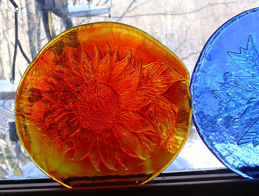
This project is for the design and construction of a electrically-heated kiln for making "Warm Glass", which is glass heated until pieces fuse together or "slump" or "drape" over shaped molds. This requires a careful profile of kiln temperature over a multi-section sequence of heating, "soaking" at a high temperature, rapid cooling to an intermediate temperature, annealing to stabilize stresses, and finally cooling to room temperature. A few examples are on the right..
external image peacock.jpg
They may be a simple as a shaped bowl, or as complex as the peacock on the right, made of hundreds of pieces. Each of these ends up as ONE piece of glass, fused together; this is not "stained glass". The Peacock is one of the more complex fused glass projects ever; it only looks like Stained Glass.
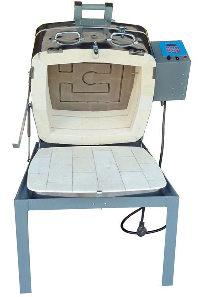
The Kiln we will use is an Olympic 149GFETLC
Glass Kiln (left). It has 3 elements, one each in the lid, midsection and bottom section. Each element is 1200 watts for a total of 3600 watts.
We need to control the elements separately.
DESIGN OBJECTIVES:>
- Arduino MEGA controller
- 4-line LCD display
- 5-button User keyboard
- 3 - MAX6675 Thermocouple Interfaces
- 3 - Type K Thermocouples in the wall of the three kiln sections
- 3 - 25 to 50 Amp Solid State Relays on heatsinks
- Power Monitor showing incoming Voltage, Current, Power, Energy Total
- Main power connect/disconnect relay for load/unload and process modes
- Auxiliary temperature controller with thermocouple, as FailSafe Watchdog.
- Arduino Sketch: (see current version HERE)
- User Interface with Keyboard and LCD, ArduinoMenu system
- Download and store Kiln Firing Schedules from USB
- User selection of Firing Schedule
- Firing Schedule interpreter driving temperature vs time profile
- Active PID control of each of the three heat zones
- Display of operation, temperatures, time
- Programmable operator notifications, allowing operator intervention
- Logging of temperature vs time for a complete process cycle.
- Network connection for remote monitoring, alerts and logging
STATUS:
Kiln received and set up. Rewired to new controller.
Successfully powered main and lid elements (240V 12 amps each) and changed duty cycle. Ran 5% duty cycle for hours with no problems, so EMC issues look good.
(See "UPDATES" at end..)
BUILD PROGESS:
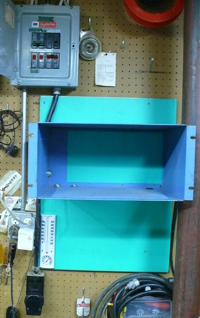
12/20..28/16 Decided to use this used 19 inch rack chassis for the controller. Mounted plywood on wall to support chassis. Close to 240V 50A connector (also used for welder and Plasma Cutter).
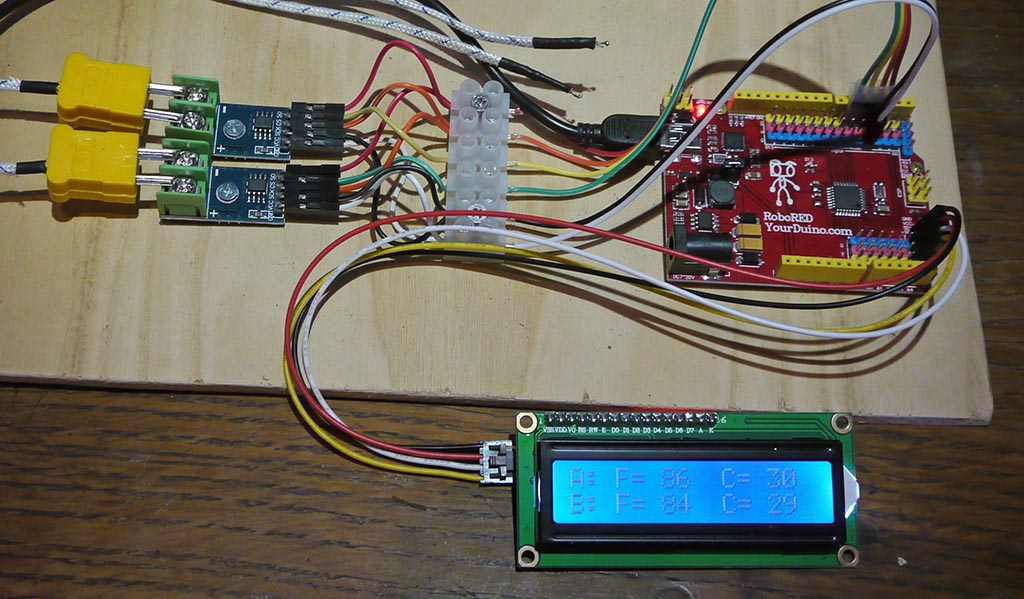
Experimented with MAX6675 Thermocouple Interfaces (How-To and code HERE)
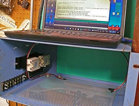
Power section was laid out, with terminal strips, cable entrances, Common Ground point, and Solid State Relays on heatsinks.
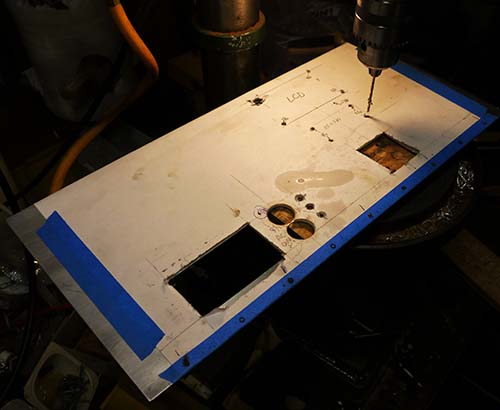
Front panel cut from .0635 (1/16 inch) aluminum.
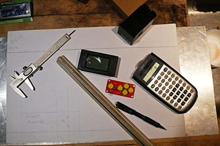
Worked on the layout, with the components and measurements in hand. The paper layout was taped to the aluminum panel and the panel was cut with a combination of drilling, chassis punches and sabre-sawing.
Below is the panel, hinged to the chassis and with some standoffs in place to mount the keyboard and LCD.
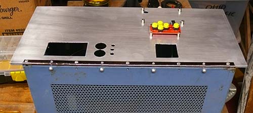
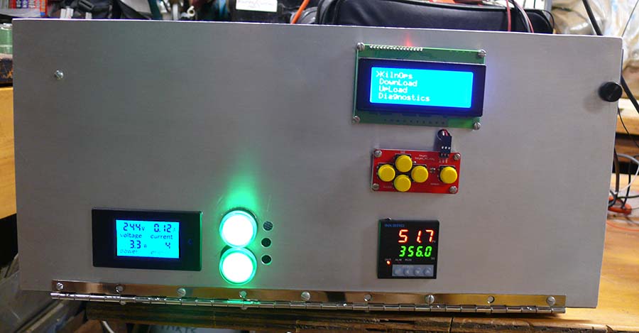
And here is the panel with some stuff working. LCD and Keyboard. Bottom left is a power monitor good for up to 50 amps at 240V (120 mA right now!) Two pilot lights on each phase of the 240. (3 holes will be pilot lights on the 3 240V kiln elements).
(3 larger White Pilot Lights like the green Line Power ones added above. )
Right is a separate thermocouple-based temperature controller used for temperature readout, and overtemperature kiln shutdown.
TIP: To make an aluminum panel look decent, 'sand' it horizontally with a "ScotchBrite" pad, dust well and then coat with automotive wax. Wait a couple minutes and buff it off, again horizontally. It won't show every fingerprint you ever put on it...
Wood Construction (Remember WOOD?):
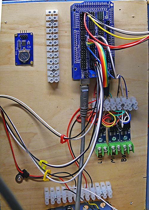
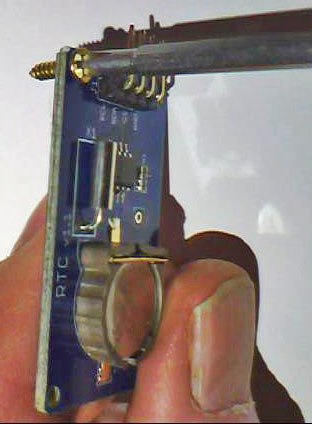
There are lots of components, such as the Arduino MEGA, MAX6675 Thermocouple interfaces. Terminal strips, Real Time Clock, etc. that need to be mechanically mounted somehow. You could carefully lay out their locations on the side of the metal chassis, drill accurate holes, insert standoffs, and put them in place with small machine screws. Too Hard! So we regress to Good Old Wood for this (which by the way is a fine insulator for 5V to 12V). Most of these "Electronic Brick" modules have Very Small holes in each corner for mounting. The challenge is to find Very Small wood screws that are 3/8" long or less. Here is an example (right) of a good size, being used for the Real Time Clock module. I think these are #4 x 3/8" screws in USA (Home Depot). And, you can Change Your Mind and move stuff around in a couple of minutes.
Metal Construction:
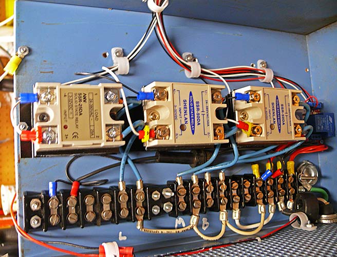
Larger, conventional components like terminal strips, heat sinks and cable entrances require holes drilled in the steel chassis. This shows the left side of the chassis, with all the high-power components.
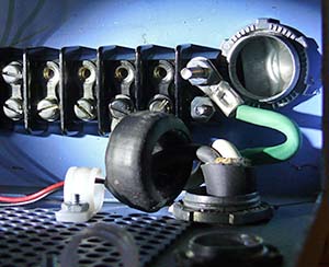
At the far right is a long bolt which connects to the steel chassis next to the main incoming power cable and it is the Common Ground Point for this system. (Closeup at left of the bolt and Green Ground wire also shows the round Current Transformer used to measure the current used by the system.) At the top are cables from the Arduino to the optically-isolated Solid State Relays. They are routed away from the high-power stuff, across the "roof" of the chassis to the Low Power / Arduino side of the system.
The Common Ground Point and Optical Isolation worked! When I had my major flash-bang-100-amp-short-circuit (see above) the Arduino Mega and components survived with no damage.
UPDATE: 25 March 2017
- Rewired elements and controller so that we have independent control of Bottom, Midsection and Lid elements
- Duty cycle 0..100 % working
- Fired kiln to 1675F for 5 hours to pre-oxidize elements
- Wrote code that does control to a desired slope (Degrees F Per Hour, Target Temperature), ran as a model
- Added code to running version to send temperature data to MeguntoPro software on PC to log and graph temperature. Working
- Running tests of temperature rise with 30, 50, 70, 90 percent power (all elements). Capturing graphs and Data.
- Built a Kiln Vent system with blower to outdoors, 4 inch metal duct to kiln, small holes in kiln floor and lid, kiln bottom connection. This dilutes the 1500F air coming from the bottom kiln vent with much added air to exit air is almost room temp.
- Rewriting code to more structured maintainable version
- Made some Thermocouples:HowTo Here
