RelayIsolation
RELAYS and OPTO-ISOLATION CONSIDERATIONS
Sometimes, when controlling lights and other loads such as motors, pumps, Solenoids etc., problems occur. Problems may include:
- Lockup of the Arduino controlling the relays and switching
- Loss of ability to communicate with a PC connected to the Arduino by USB
- Noise and erroneous readings on sensors or attached devices when relays or loads are switched
There are several things to consider here:
- Isolation of Arduino from the relays themselves and their switching transistors and power supply
- Isolation of your power wiring from arduino and it's wiring
- Creating a "Common Ground Point" (usually the negative terminal of your power supply)
- Grounding your Arduino system Common Ground Point to the building ground
Let's look at the choices of relay boards. There are two widely available types of relay boards, and lately they cost about the same.
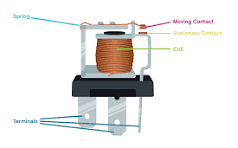
- Relays of all types. Example HERE:
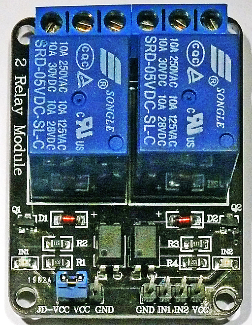
- Boards with optical isolation that can be run with no direct electrical connection between Arduino and the relays and their power supply, shown below. Example HERE:
Boards like this are available with 1,2,4 or 8 relays.
Optical Isolation
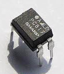
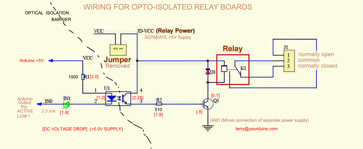
"Optically Isolated" means an "Opto-isolator" chip is used. See: http://en.wikipedia.org/wiki/Optoisolator So only a beam of Infrared light (The little blue arrows in the diagram below) connects the Arduino circuitry to the relay and switching parts. Here's what an opto-isolated board looks like, followed by it's circuit diagram, and a photo of the opto-isolator chip:
 This is the Opto-Isolator chip used on these relay boards. More details are here: https://arduinoinfo.mywikis.net/wiki/Popular-ICs#PC817_Opto-Isolator.
Now, let's look at how to connect the relay board so it is really isolated. Notice that board has a jumper between "Vcc" and "JD-Vcc". Remove it.
For complete optical isolation, connect "Vcc" to Arduino +5 volts but do NOT connect Arduino Ground.
Connect your Arduino Digital Output pins to "IN0", "IN1" etc.
Connect a separate +5 supply to "JD-Vcc" and board Gnd. This will supply power to the transistor drivers and relay coils.
Look at the diagram above. Only the part to the left of the small blue arrows is connected to Arduino.
Wiring and cabling issues:
You're not home free yet, because if you are switching large loads, especially inductive loads like motors, etc. you may still have "EMI" (ElectroMagnetic Interference) problems.http://en.wikipedia.org/wiki/Electromagnetic_interference
People who have designed computer-driven automated machinery know that they have to be careful about the physical routing, shielding, and isolation of low-level computer/Microcomputer electronics and high-power motors and loads. Here are a few guidelines:
- Physically separate the low-power Computer/Electronics part from the large power-handling part
- Pay special attention to Grounding: Create a single common ground point in the power section. Connect the Computer/Electronics ground to it at only that one point.
- If possible locate all the power switching devices/relay in the power section, as close to the load as reasonable
- Run connections to the relays etc. from the Computer section to the Power section in shielded twisted pair (or at least twisted pair) wiring.
- Minimize the Electromagnetic Interference put out by the loads by putting suppression devices across them to absorb the energy put out as they are disconnected or switched Off. Here are some examples:
- MOVs (Metal Oxide Varistors) conduct at some higher-than-supply voltage. Good for fast voltage spikes etc.
- DC Loads like solenoids used in electrical valves, and Motors, should have a diode connected in the Reverse direction across them. This will absorb the reverse-voltage spike/transient voltage that occurs when they are switched Off.
- Some loads that have to act very fast may be slowed down by a reverse diode, and need a specially-calculated series Resistor-Capacitor network connected across them.
- Test the switching by attaching a simple light bulb load. When everything works, try the real heavy load. Then you will know if you have EMI problems.
OK, that's a big deal. What can we do that's simple and helps? I'd suggest this:
- Locate the relay board close to the load, (like in the outlet example)
- Locate a separate 5V supply near the relay boards, plugged into the Load power, not near the Arduino power supply or a computer supplying USB power to Arduino.
- Run CAT5 cable back to Arduino, one pair for +5V and Arduino ground (NOT connected on the relay end if you have opto-isolated relays), One pair for each signal, with one wire connected to ground at Arduino, the far end unconnected
- Run the Arduino from a separate 9V supply, not USB connected to a computer
- Connect the Arduino Power Supply Ground to building ground. You can connect a single ground wire to the "Green Ground" connection in an AC plug and plug it into the wall (Nothing connected to the Line and Neutral connections)..
- Suppress the EMI from troublesome loads like motors and solenoids by connecting a MOV (Metal Oxide Varistor) or other suppression device across the load.
More about power/relays here: ArduinoPower Lots of relays HERE. Lots of people are successfully controlling lighting, home devices, complex aquariums, Aquaponic Systems , etc etc. with relays like this. If you are having problems, please email [1] And, if you SOLVE a problem like this, also let Terry know to add to the knowledge about these problems..


