RobotKitMenu-1-C
[/RobotKitMenu-C BACK to MENU]

START: YOURDUINO BASIC ROBOT KIT
FOR CHROMEBOOK!
Please email comments, critiques, suggestions and questions to: terry@yourduino.com
The OLDER Version 1 Info(Click HERE):
This section will help you get the Arduino Online software installed, and have a first look at programming the YourDuino RoboRED Microcomputer that will control your robot. Oh: What's an Arduino Anyway?? See HERE:
I have Arduino working, I know all this and I want to just Build The Robot! [/RobotKitMenu-2-C (SKIP AHEAD)]
Unpacking Your Robot Kit and getting out a few parts: GO HERE: and then return.
GETTING STARTED
To program the Arduino on your Chromebook you will use an entirely web based app, Arduino Create. This app was built to run in the Chrome Browser, and because of this runs seamlessly on the Chromebook. We call the place that we write code an IDE. So from now on were going to call the programming app the Create IDE.

  Oh.. "What's this IDE thing all about anyway" ?? The Integrated Development Environment is the software you use on your computer to write software Sketches and then upload and run them on the YourDuino hardware. The IDE is like a word processor for writing software.

  Unfortunately unlike the normal Arduino IDE, the Create IDE isn't free, for individuals it is 1 dollar per month. There are classroom versions available, which range from $0.40 to $0.20 per student. depending on how many students you have. However if you just want to try it out there is a 5 day free trial.

  To use the Create IDE on the Chromebook we will need THIS  plugin. Once it is installed you can go to the Arduino Create and make an account. Make sure to use the same email as you used for your Chromebook. This will make everything work together much better. Once you are set up click on the menu icon in the upper left hand corner of Arduino Create, then pick the Arduino Web Editor.
MY Arduino / YourDuino board is board is already installed!
OK, (CONTINUE BELOW)

CHECK OUT THE NEW YourDuino RoboRED:
The new YourDuino RoboRED is now used in these Starter Kits. It is equivalent to an Arduino UNO, but has added features.
  NOTE: The RoboRED MAY have a switch labelled 3V3 5V that can change the operating voltage. Usually there will be a jumper that is to the Right for 5V. If you have the switch make SURE it is in the 5V position as shown.
  Near the upper left is the PWR LED which should light up whenever the board is plugged into a USB connection, or has power from an external power supply.
  At the upper left there are two added red LEDs which will blink when a software sketch is being uploaded to the board, or other data is being transferred over USB.
  In the center is a red LED which is internally connected to pin 13 through a current-limiting resistor. It should blink after you load the example BLINK software sketch. The colored 3-pin connectors on every I/O Pin make it easy to connect many input and output devices. Vcc(+5V) pins and (Ground) pins with every I/O pin are good for connections to breadboards etc.
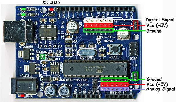 CHECK OUT THE YourDuinoRobo1:

NOTE: This version was used in earlier YourDuino Kits and is here for reference if you have one of these. On the right, let's look at some of the features of the Robo1 board as used in these Starter Sets. At the lower left is the PWR LED which should light up whenever the board is plugged into a USB connection, or has power from an external power supply.
  At the upper left there are two green LEDs which will blink when a software sketch is being downloaded to the board, or other data is being transferred over USB.
  At the top is a red LED which is internally connected to pin 13 through a current-limiting resistor. It should blink after you load the example BLINK software sketch. The colored 3-pin connectors make it easy to connect many input and output devices. The Vcc(+5V) pins at upper right and the (Ground) pins at the lower right are good for connections to breadboard etc.

  Soon we'll start connecting the things in the Kit, but first we'll use that built-in Pin 13 LED to get started. You'll see how to edit Software Sketches and change the way hardware reacts.
"SOFTWARE TIME" : WRITING ARDUINO SKETCHES
Let's take a little while to get used to writing Arduino Software, then we'll come back and start connecting your Robot kit parts and making more interesting things. We will give you software examples to test each part of the Robot kit.

  You should have the Create IDE up and running now. Lets walk through the features of the IDE.

  You'll use this IDE (Integrated Development Environment) to make Software VISIBLE! With it you will develop your own software to make Arduino into what you want it to be.
FIRST, YOU MUST SET THE CORRECT BOARD TYPE:
In the create IDE click on the select board or port drop down. 
This will open the board selection window.

Scrole down until you find the board you want, then click OK. NOTE: For the YourDuino RoboRED in all current kits, pick "Arduino UNO". For the older YourDuinoRobo1 click Arduino Duemilanove.
Now you will see this:  This means that the board has been selected but there is no arduino connect. Now take your Arduino Board and plug it in to Chromebook. It should now look like this:
  Which shows that the Arduino is connected to the Create IDE and you should be able to upload sketches.
SKETCHES:
The visible text of an Arduino software program is called a SKETCH. But the Sketch becomes alive when you upload it to your Arduino. Let's walk through Editing a Sketch and Verifying it and Uploading it:
On the panel on the left hit examples, then basics, then click on Blink. There are lots of examples that come with the Create IDE, and we will look at some of them later, as well as make our own very soon.
Your screen should now look like this:
Wow.. A bunch of new stuff.
Let's slow down and "Watch Closely Now"!
Notice that a lot of the text is GRAY. All of that is just "Comments" for you to read to help understand the Sketch. When you write software, you should also use "Comments" to explain to others what you are doing. (Arduino itself totally ignores these comments).
Now, let's go through Editing software, Verifying it, and Uploading it to see Arduino DO it. We will use the YourDuino version of Blink: YourDuinoStarter_Blink . Click on the link to see it's page.
Now, highlight all the code (in the gray area) , do <Ctrl>C to Copy. In the IDE, go to the Sketchbook tab, and click New Sketch. Get rid of everything already in the IDE and do <ctrl>V to Paste in the code from the website. Click Verifyto make sure it's OK. You should see "Compiling Sketch" and then "Compiling Done". Now look at the sketch in detail. Take some time to read it slowly.


STRUCTURE OF ARDUINO SOFTWARE:
Every Arduino Software Sketch has two main parts:
- SETUP - Runs Once at the beginning
- LOOP - Runs over and over again, forever
You will read a LOT of program "Code" that other people wrote, in the future. You HAVE to "Watch Closely Now" and really see the details. Read the YourDuinoStarter_Blink example through carefully, a couple of times. Note the colored special words that are Instructions . These are unique words that tell Arduino what to do. They have to be spelled perfectly!
What SETUP does: Tells Arduino about things that need to be done once. Arduino Digital Pins can be either INPUT or OUTPUT. You have to tell Arduino when a Pin will be used as an OUTPUT. In this example, there is one line that tells Arduino that Pin 13 must be an OUTPUT.
![]()
Note the COLOR of the lettering. The Arduino IDE changes the color of words as it recognizes them as special instructions. Let's mess with them:
pinMode: Note that when Instructions are two words run together, like pinMode, the beginning of the SECOND word is Capitalized. Change the Capital "M" to "m". Note the color changes to black. Hmmm. Click the VERIFY button.
You will get an ERROR message: ![]()
Fussy, Fussy, Fussy! Yep, every letter has to be correct and also correct upper or lower case.
Change it back. Check the color. Click Verify again. OK??
What LOOP does: Loop contains all the active parts of your Sketch that continue to run after SETUP is finished. It will run over and over again, forever, or until you stop it or power down.
What does VERIFY do??
A LOT! More details later, but Verify is a program in your main computer that goes through every Instruction in your Sketch (Ignoring "Comments") and checks it against the list of valid Instructions, and checks that the structure and sequence of the statements in the Sketch are correct. Fussy, Fussy! If they're OK, then it "compiles" or "translates" the sketch into the machine code that Arduino actually runs on. It saves that 'ready-to-run' code for you to Upload to Arduino and run. Other systems would call this process "Make" or "Compile". Arduino refers to it as "Build" and if you want the gory details (Click Here).
What does UPLOAD do?? 
First, Upload runs Verify to check and compile your program. Then it communicates to your Arduino over the USB connection, resets the Arduino chip, and talks to software already on Arduino (called the BOOTLOADER(W)) to load your new program into the Arduino's memory. Then it restarts Arduino and your program runs it's SETUP section and then repeats the LOOP section.
[NOTE: The (W) Means this is a Wikipedia link.]
Start Making Changes:
Ok, let's make a few changes to the YourDuinoStarter_Blink program:

The LOOP section of your program does all the instructions in the section, and then "loops" back to the top and starts it again, over and over.
NOTE: the "Brackets" { and }
Notice that the beginning and end of the section is "inside brackets". You will see many sections of bigger programs that are grouped by these "brackets".
Now, let's look in detail at the instructions:
Instruction: digitalWrite
This instruction sets an OUTPUT PIN to either HIGH (connects it to +5 V) or LOW (Connects it to GND). Lots of new words will be thrown about here!
Thing To Remember: HIGH = 1 = ON = 5 Volts and LOW = 0 = OFF = 0.0 Volts
So, the first line in LOOP sets PIN 13 to HIGH. This means Pin 13 is connected to +5 Volts, and current flows through a resistor and LED that are already connected to pin 13 on the Arduino board. The LED lights up.
Instruction: delay
The delay instruction just waits for a period of time. The VALUE used with delay is in Milliseconds (1/1000 second). So delay(1000); waits for 1000/1000 seconds (1 second). We'll change that soon.
NOTE: the ";" (Semi-Colon)
Notice that every instruction is followed by the character " ; " which is like a period that tells the end of a sentence. Run-on sentences will make you stay after school to fix your error messages!
Change the delay so that the LED blinks differently:
Time to mess about and try some things! Maybe we'll break it. Then we'll fix it..
Suggestion: Save your own version of BLINK so you can always go back to the original one. Go to File and Save As and call it something like MyBlink. This will go in your SKETCHBOOK where you'll save your own programs.
Now go change the VALUE in a delay statement to change the way the LED blinks. Think about the 4 instructions in LOOP. What's happening??
- Turn the LED on. Wait and look at the LED.
- Turn the LED off. Wait and look at the dark.
So, let's change the ON time to be short. Maybe 50 Milliseconds. That's 1/20 of a second. Change the first delay instruction to be delay(50);
Then try 10 milliseconds. The LED is only on 1/100 of the time. Can you still see it blink? How about 1 millisecond?
Each time you make a change, click Upload which will first Verify and Compile your program and then send it to Arduino. Notice that each time you do this the LEDS on the Arduino board that are marked "Tx" (Transmit) and "Rx" (receive) flash as your main computer communicates with your Arduino.
Try out some combinations of ON and OFF delay() times. Like ON 1000 and OFF 50.
Try making both ON and OFF times shorter and shorter. If you make the ON and OFF times short enough your eye will no longer see blinking, because of "Persistence of Vision"(W) which happens when there are more than about 25 blinks per second. So, hmmm.... if you make the LED be ON for 1/50 of a second and OFF for 1/50 of a second that should do it. So try 1000/50= 20 Milliseconds. Put 20 for both the ON and OFF times. What do you see?? How about 10 Milliseconds each? Depending on your personal eye's physiology, at some speed you will not see any more blinks. Young people can usually see faster blinks than old codgers like me :-)
ASIDE: This control of brightness/power by changing the ON time vs the OFF time is called Pulse Width Modulation (PWM) Arduino has a built-in capability of doing it with the analogWrite command.
All right. You are hacking code. You're the Programmer! You can save any of the sketches for use later on. You can save your sketch for later by clicking here,  and hitting save.
Next, we'll start hooking up the Parts in your Robot Kit! And we'll give you example Software Sketches for each one of them.
Go To the Next Section: [/RobotKitMenu-2-C MicroComputer Software]
OR back to the [/RobotKitMenu-C#SBS Main Menu]:
Please email comments, critiques, suggestions and questions to:
  terry@yourduino.com