RobotKitMenu-4
CONTROLLING MOTION, SENSING DISTANCE:
NOTE about POWER:
Many newer computers and most laptops and tablets limit the power available on the USB cable. This robot will usually need to run from the external Battery Case with 6 AA batteries. So in some cases you will have to have the battery connected to use the USB to upload sketches.
I want to just Build The Robot! (SKIP AHEAD)
In this section you'll learn about the Servo Motor used in the Robot, connect it and make it move. Then you'll learn about the Ultrasonic Distance Sensor, connect it and test it. You'll be ready to add those together to the Robot Base later.
Servo:
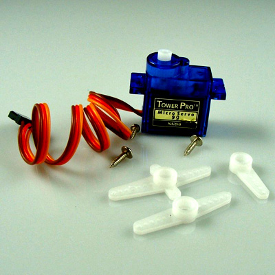
Servos are small box-shaped electro-mechanical devices that contain a DC motor, electronics to control the motor from a signal, a gear system to produce slow/strong output to a shaft, and a position feedback potentiometer. They are Positional devices: they move an output arm to different positions as commanded by a signal. They are not (usually) continuous-rotation devices. There are a variety of sizes and weights, of similar construction. They are widely used in Model cars and airplanes, and can cost as little as $3.50 More details HERE.
Servos usually come with several different arms you can attach depending on your design. Usually you use a Servo to position something, like steering direction, arm/leg movement etc. In this Robot the servo is used to point the Ultrasonic Distance Sensor in different directions, like a person "looking around".
For most servos the position angle of the servo is controlled by the length of the pulse in milliseconds (usually between about 1.00-2.00ms). 1.50ms is usually Center.
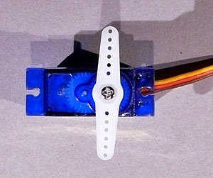
Open the small bag with servo arms and screws. Attach the long white arm to the top of the servo as shown in the photo. Orient the servo with the wire to the right.
- Lightly push the white servo arm onto the servo shaft. (Don't put a screw in yet).
- Carefully turn the arm counter-clockwise until it stops
- Remove the arm and reposition it so that it is oriented at right angles (as shown). It is now pointing "Left". Do not put the screw in yet.
OK, now let's make it work. All RC servos have a three wire connector. One wire supplies positive DC voltage – usually 5 to 6 volts. The second wire is for ground, and the third wire is the signal wire. The Arduino “talks” to the servo through this wire by means of a simple on/off pulsed signal. They can plug directly into the 3-pin connectors on a YourDuino RoboRED or a SensorShield.
CONNECTIONS:
- wire colors may vary!
- Servo Black or Brown to Ground
- Servo Red or Orange (Center wire) to +5V
- Servo White or Yellow to Signal (Pin 11)
You should have your RoboRED plugged in with USB, and have run BLINK successfully.
NOTE: The RoboRED also has a switch labelled 3V3 5V that can change the operating voltage. Make SURE it is in the 5V position.
SKETCH TO TEST SERVO MOTION: The SERVO library is part of the regular Arduino software installation. We will use a sketch similar to the example called "Sweep" which will move the servo through its range of movement.
Plug in the USB Cable to be ready to upload this software sketch. Do NOT plug the servo in yet; you'll need to use the battery case power.
HOW TO COPY/PASTE SOFTWARE SKETCHES:
You will Copy and Paste the Software Sketches below to test and run your robot. Here's how:
- On this page, position your mouse cursor just before the beginning of a sketch, then hold the left button down and move slowly down over the sketch and over the end " //*( THE END )*"
- Press <Ctrl> C to COPY. (<Command> C on MAC)
- Switch to the Arduino IDE software.
- Click on File > New (You will get a new window)
- Use your mouse cursor and left button to highlight the small example shown there. Leave it highlighted so you will replace it.
- PASTE the sketch by pressing <Ctrl> V (<Command> V on MAC)
- Check that the beginning and end of the sketch are right.
- Click Verify on the IDE and make sure there are no errors. If problems, see "About Libraries" Here.
- Click Upload
 on the IDE with your USB cable connected and the right Port selected. It should say "Compiling Sketch" and then "Uploading Sketch" and then "Upload Complete". You should see the Tx and Rx LEDs on the RoboRed board blink for a second or two during the actual upload..
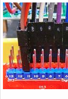
Now Unplug the RoboRED (which you should do whenever making connections). and then plug the Servo onto the 3-pin connector at I/O Pin 11. (see photo above). Easier to count Down: 13-12-11. The brown wire should plug on the G (ground) (Blue) pin. Now plug the battery case with batteries into the RoboRED external power connector. The servo should "look around" back and forth. It will keep going until you unplug the YourDuino or upload a different Sketch. (When you want to stop the servo motion unplug it and just upload Blink again.)
/* YourDuino Basic Robot Kit V2: Test Servo movement
 - WHAT IT DOES: Tests the servo by commanding it to go to several different directions
   to "Look Around". You may want to reposition the servo arm on the servo to get the
   positions to look around correctly.
 - SEE the comments after "//" on each line below
 - CONNECTIONS:
   -
   -
 - V2.13 05/15/2017 Limit extreme positions
   Questions: terry@yourduino.com */

/*-----( Import needed libraries )-----*/
#include <Servo.h>

/*-----( Declare Constants and Pin Numbers )-----*/
#define SERVO_PIN 11 // Servo plugs into Pin 11

/*-----( Declare objects )-----*/
Servo myservo;  // create servo object to control a servo

/*-----( Declare Variables )-----*/
int pos;    // variable to store the servo position

void setup()   /****** SETUP: RUNS ONCE ******/
{
  myservo.attach(SERVO_PIN);  // attaches the servo on pin 11 to the servo object

}//--(end setup )---


void loop()   /****** LOOP: RUNS CONSTANTLY ******/
{
  for(pos = 20; pos < 160; pos += 28)  // goes from 20 degrees to 160 degrees
  {                                  // in steps of 30 degree
    myservo.write(pos);              // tell servo to go to position in variable 'pos'
    delay(1000);                      // Wait 1000ms between pings
  }

  for(pos = 160; pos>=20; pos -= 28)     // goes from 160 degrees to 20 degrees
  {
    myservo.write(pos);              // tell servo to go to position in variable 'pos'
    delay(1000);
  }

}//--(end main loop )---

/*-----( Declare User-written Functions )-----*/
//NONE

//*********( THE END )***********
Ultrasonic Distance Sensor:
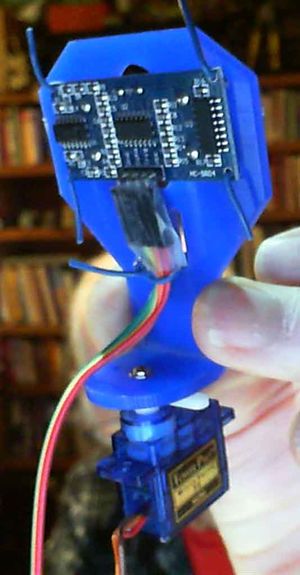
(Unplug the servo for now) Get the plastic bracket that will hold the Ultrasonic Sensor(below):
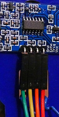
Attach 4 wires from the rainbow cable, (use Red, Orange, Yellow and Green) to the base of the ultrasonic sensor (As shown in the closeup photo of the back of the Ultrasonic Sensor.
Cut 3 pieces of the thin blue wire about 2 Inches (5cm) long. Place the Ultrasonic Sensor into the blue bracket from the back (bottom bracket side), and secure it with two pieces of the blue wire. Be sure to get the wire through the holes in the sensor.Use another piece of wire to secure the cable to the bracket through the two vertical cutouts.
| ConnectionsUltrasonic-200.jpg |
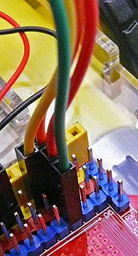
Connect the cable from the Ultrasonic Sensor to the RoboRED as shown at right. Use the 3-pin connector for pin 2. Numbers start at D0, D1 D2. Green to pin 2 GND (blue row), Red to Pin 2 Voltage (red row), Orange to Pin 2 Signal (yellow row), and finally Yellow to pin 3 Signal (yellow row). This connects the sensor Ground, Voltage, Trigger and Echo wires.
We will use a library called NewPing written by Tim Eckel to run the Ultrasonic Sensor. You will need to download and install the NewPing library. You can find the NewPing library zip file HERE and download it. Remember where you saved it.
Then install the new library as shown HERE:.
Then copy, paste, upload and run the test sketch below.
Note: The sketch will send the distance measurements it is making to the "Serial Monitor," which is a window you can start by clicking on the "serial monitor" icon at the upper right of the IDE window.
![]() Put your hand or other object in front of the Ultrasonic sensor and move it farther and closer and you should see the distance displayed on the Serial Monitor.
Put your hand or other object in front of the Ultrasonic sensor and move it farther and closer and you should see the distance displayed on the Serial Monitor.
/* YourDuino Basic Robot Kit V2: Ultrasonic Sensor Test
 - WHAT IT DOES
   - Tests the operation of the Ultrasonic Sensor
 - SEE the comments after "//" on each line below
 - CONNECTIONS: (suggest cable with 4 wires: Red,Orange,Yellow,Green )
 - Sensor Vcc to RoboRED     Vcc     (Red)
 - Sensor Ground to RoboRED  Gnd     (Green)
 - Sensor Trig to RoboRed    pin 2   (Orange)
 - Sensor Echo to RoboRED    pin 3   (Yellow)
 - V2.10 11/10/2014
 Questions: terry@yourduino.com */

/*-----( Import needed libraries )-----*/
#include <NewPing.h>

/*-----( Declare Constants and Pin Numbers )-----*/
#define TRIGGER_PIN  2   // Arduino pin tied to trigger pin on the ultrasonic sensor.
#define ECHO_PIN     3   // Arduino pin tied to echo pin on the ultrasonic sensor.
#define MAX_DISTANCE 200 // Maximum distance we want to ping for (in centimeters). Maximum sensor distance is rated at 400-500cm.

/*-----( Declare objects )-----*/
NewPing sonar(TRIGGER_PIN, ECHO_PIN, MAX_DISTANCE); // NewPing setup of pins and maximum distance.
/*-----( Declare Variables )-----*/
unsigned int uS;

void setup()   /****** SETUP: RUNS ONCE ******/
{
  Serial.begin(9600); // Open serial monitor at 9600 baud to see ping results.

}//--(end setup )---


void loop()   /****** LOOP: RUNS CONSTANTLY ******/
{
  delay(50);                      // Wait 50ms between pings (about 20 pings/sec). 29ms should be the shortest delay between pings.
  uS = sonar.ping(); // Send ping, get ping time in microseconds (uS).
  Serial.print("Ping: ");
  Serial.print(uS / US_ROUNDTRIP_CM); // Convert ping time to distance in cm and print result (0 = outside set distance range)
  Serial.println("cm");

}//--(end main loop )---

/*-----( Declare User-written Functions )-----*/
//NONE

//*********( THE END )***********
Attach the Ultrasonic Sensor and Bracket on top of the Servo arm:
- Push the white servo arm firmly in place. Carefully rotate it fully counterclockwise as shown above. Align the blue bracket for the Ultrasonic Sensor on top of the servo arm, the front of the bracket should be parallel to the white servo arm .
- Switch your screwdriver to "Phillips" end. Use one of the 2 longer small screws in the package to secure the bracket, the white arm and the servo shaft. Put the screw down through the center hole of the bracket base and into the center hole in the servo shaft. Point the ultrasonic sensor to the left (away from the servo wires).
- Tighten the screw just enough that the bracket stays aligned with the white arm.
OK! If that's all working OK, you'll go ahead now to build the Robot Base with wheels, motors etc. and then add the RoboRED and the Servo/Sensor Shield assembly you just built.
To the Next Section: Build The Robot Base OR back to the Main Menu
Please email comments, critiques, suggestions and questions to:terry@yourduino.com
